


BBV28581 05/2010 109
Diagnostics and Troubleshooting
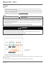
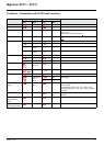
Fault detection codes that can be cleared with the automatic restart function, after
the cause has disappeared
These faults can also be cleared by turning on and off or by means of a logic input (parameter Detected fault reset assignment rSF
page 91
).
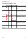
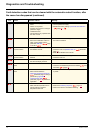
Code
Name Possible causes Remedy
LFFI AI current lost fault Detection if:
• Analog input AI1 is configured as
current
• AI1 current scaling parameter of
0% CrL1 page 52
is greater
than 3 mA
• Analog input current is lower than
2 mA
• Check the terminal connection
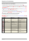
ObF Overbraking • Braking too sudden or driving load
too high
• Increase the deceleration time
• Install a module unit with a braking resistor if necessary
• Check the line supply voltage, to be sure that it is under
the maximum acceptable (20% over maximum line supply
during run status)
OHF Drive overheat • Drive temperature too high • Check the motor load, the drive ventilation and the
ambient temperature. Wait for the drive to cool down
before restarting. See Mounting and temperature
conditions page 13
.
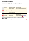
OLC Process overload • Process overload • Check the process and the parameters of the drive to be
in phase
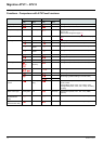
OLF Motor overload • Triggered by excessive motor
current
• Check the setting of the motor thermal protection, check
the motor load.
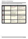
OPF1 1 output phase loss • Loss of one phase at drive output • Check the connections from the drive to the motor
• In case of using downstream contactor, check the right
connection, cable and contactor
OPF2 3 output phase loss • Motor not connected
• Motor power too low, below 6% of
the drive nominal current
• Output contactor open
• Instantaneous instability in the
motor current
• Check the connections from the drive to the motor
• Test on a low power motor or without a motor: In factory
settings mode, motor phase loss detection is active
Output Phase loss detection OPLpage 94
= YES. To
check the drive in a test or maintenance environment,
without having to use a motor with the same rating as the
drive, deactivate motor phase loss detection Output
Phase loss detection OPL = nO
• Check and optimize the following parameters: IR
compensation (law U/F) UFr page 58
, Rated motor
voltageUnS page 57
and Rated motor current nCr
page 57
and perform an Auto-tuning tUn page 60.
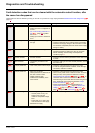
OSF Main overvoltage • Line voltage too high:
- At drive power on only, the
supply is 10% over the
maximum acceptable voltage
level
- Power with no run order, 20%
over the maximum line supply
• Disturbed line supply
• Check the line voltage