


24 BBV28581 05/2010
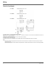
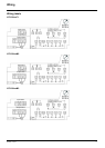
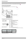
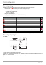
Control terminals
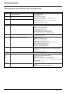
Characteristics and functions of the control terminals
Terminal Function Electrical characteristics
R1A NO contact of the relay Min. switching capacity:
• 5 mA for 24 V
c
Maximum switching capacity:
• 2 A for 250 V
a and for 30 V c on inductive load
(cos ϕ = 0.4 and L/R = 7 ms)
• 3 A for 250 V
a and 4 A for 30 V c on resistive load
(cos ϕ = 1 and L/R = 0)
• response time: 30 ms maximum.
R1B NC contact of the relay
R1C Common pin of the relay
COM Common of analog and logic I/Os
AI1 Voltage or current analog input • resolution: 10 bits
• precision: ± 1% at 25°C (77°F)
• linearity: ± 0.3% (of full scale)
• sampling time: 20 ms ± 1 ms
Analog voltage input 0 to +5 V or 0 to +10 V
(maximum voltage 30 V) impedance: 30 kΩ
Analog current input x to y mA, impedance: 250 Ω
5V +5 VDC power supply for reference potentiometer • precision: ± 5%
• maximum current: 10 mA
AO1 Voltage or current analog output (collector) • resolution: 8 bits
• precision: ± 1% at 25°C (77°F)
• linearity: ± 0.3% (of full scale)
• refresh time: 4 ms (maximum 7 ms)
Analog voltage output: 0 to +10 V (maximum voltage +1%)
• minimum output impedance: 470 Ω
Analog current output: x to 20 mA
• maximum output impedance: 800 Ω
LO+ Logic output • voltage: 24 V (maximum 30 V)
• impedance: 1 kΩ, maximum 10 mA (100 mA in open collector)
• linearity: ± 1%
• refresh time: 20 ms ± 1 ms.
LO- Common of the logic output (emitter)
LI1
LI2
LI3
LI4
Logic inputs Programmable logic inputs
• +24 VDC power supply (maximum 30 V)
• impedance: 3.5 kΩ
• state: 0 if < 5 V, state 1 if > 11 V in positive logic
• state: 1 if < 10 V, state 0 if > 16 V or switched off (not connected)
in negative logic
• sampling time: < 20 ms ± 1 ms.
+24V + 24 VDC supply provided by the drive + 24 VDC -15% +20% protected against short-circuits and
overloads.
Maximum customer current available 100 mA