


84 BBV28581 05/2010
Configuration Mode - Complete menu (FULL)
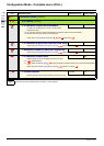
Pump sub-menu PMP
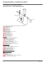
The principal objective is to control a complete pumping installation using a single ATV12 drive by providing constant pressure whatever
the flow rate.
The system is operated using an auxiliary fixed speed pump, and one variable speed pump, which is unable to provide the full flow range
required on its own. A PI regulator is used for drive control. The pressure sensor provides system feedback.
The variable speed pump is called a variable pump.
The fixed speed pump is called an auxiliary pump.
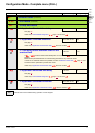
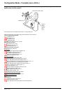
Selecting the operating mode
The ATV12 offers 2 operating modes:
• Single variable mode: 1 single variable speed pump (variable pump).
• Single variable with auxiliary pump mode: 1 variable speed pump (variable pump) and one fixed speed pump (auxiliary pump).
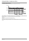
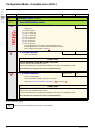
Control of the auxiliary pump
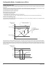
The PI regulator output (frequency reference of the variable pump) is used to control starting or stopping of the auxiliary pump with
hysteresis, as shown in the figure below:
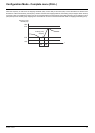
When the frequency exceeds the starting threshold (FOn), a time delay (tOn) is launched to avoid the effects of transient flow fluctuations.
If after this time delay, the frequency remains higher than the starting threshold, the auxiliary pump is started. When the start command is
sent, the variable pump will go from its current speed reference to the auxiliary pump stopping frequency (FOF) following a ramp (rOn) that
equals the time taken for the auxiliary pump to reach its nominal speed. Parameter rOn is used to minimize the booster effect on starting
the auxiliary pump.
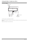
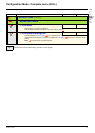
Frequency of the
variable pump
Auxiliary pump starting
Auxiliary pump
stopping
Frequency
corresponding to the
auxiliary pump flow
rate
HSP
Starting frequency
FOn
Stopping frequency
FOF
Flow rate of the installation
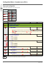
HSP
FOn
FOF
tOn
LSP
rOn
0
t
F
requency o
f
th
e
variable pump
Auxiliary pump starting