


BBV28581 05/2010 23
Control terminals
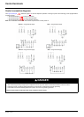
Keep the control circuits away from the power cables. For control and speed reference circuits, we recommend using shielded twisted
cables with a pitch of between 25 and 50 mm (1 and 2 in.), connecting the shielding as outlined on page 26
.
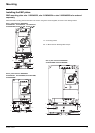
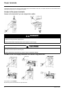
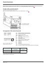
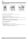
Access to the control terminals
To access the control terminals, open the cover.
Note: For information regarding HMI button functions, see "HMI description" on page 32.
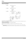
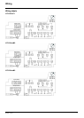
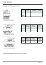
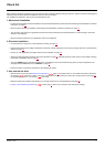
Arrangement of the control terminals
It is possible to lock the
cover with a lead seal.
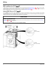
Note: To connect cables, use a
slotted screwdriver 0.6 x 3.5.
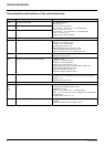
R1A
R1B
R1C
COM
AI1
5V
AO1
LO+
LO-
COM
LI1
LI2
LI3
LI4
+24V
RJ45
RJ45
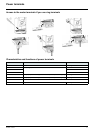
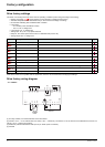
(1)The value in bold corresponds to the minimum wire gauge to permit secureness.
(2)Recommended to maximum value.
ATV12 Control terminals Applicable wire size (1) Tightening torque (2)
mm² (AWG) N·m (lb.in)
R1A, R1B, R1C 0.75 to 1.5 (18 to 16)
0.5 to 0.6 (4.4 to 5.3)
Other terminals 0.14 to 1.5 (26 to 16)
Normally open (NO) contact of the relay
Normally closed (NC) contact of the relay
Common pin of the relay
COMmon of analog and logic I/Os
Analog Input
+5VDC supply provided by the drive
Analog Output
Logic Output (collector)
Common of the Logic Output (emitter)
COMmon of analog and logic I/Os
Logic Input
Logic Input
Logic Input
Logic Input
+24 VDC supply provided by the drive
Connection for SoMove software, Modbus network or remote display.