


BBV28581 05/2010 51
Configuration Mode - Complete menu (FULL)
Code
Name/Description Adjustment range Factory setting
I_O-
Input Output menu (continued)
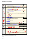
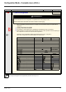
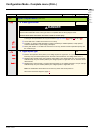
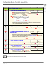
tCt
M 2 wire type control
trn
LEL
trn
PFO
DANGER
UNINTENDED EQUIPMENT OPERATION
Check that the modification of the 2 wire type control is compatible with the wiring diagram used.
Failure to follow these instructions will result in death or serious injury.
2-wire type control parameter can only be accessed if Type of control tCC page 48 is set to 2C.
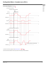
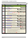
v Level: State 0 or 1 is taken into account for run or stop.
v Transition: A change of state (transition or edge) is necessary to initiate operation, to help prevent
accidental restarts after a power supply interruption.
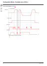
v Priority FW: State 0 or 1 is taken into account for run or stop, but the "forward" input takes priority over
the "reverse" input.
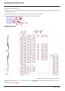
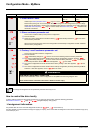
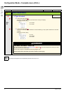
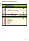
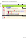
nPL
M Logic inputs type
POS
POS
nEG
EnEG
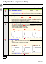
v Positive: the inputs are active (state 1) at a voltage equal to or higher than 11 V (for example +24 V
terminal). They are inactive (state 0) when the drive is disconnected or at a voltage lower than 5 V.
v Negative using internal supply: the inputs are active (state 1) at a voltage lower than 10 V (for example
COM terminal). They are inactive (state 0) at a voltage equal to or higher than 16 V or when the drive is
disconnected.
v Negative using external supply : the inputs are active (state 1) at a voltage lower than 10 V (for example
COM terminal). They are inactive (state 0) at a voltage equal to or higher than 16 V.
Note: The modification will be taken into account only at the next control power on.
See Control connection diagrams, page 25.
I-O-
drC-
CtL-
FUN-
FLt-
COM-