


114 BBV28581 05/2010
Application notes
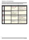
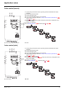
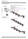
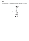
2-wire control (sink)
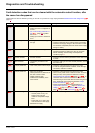
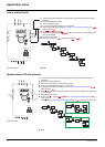
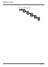
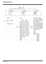
Speed control 0-20 mA (source)
(a): Run Forward
1. Connect the ground terminal to the grounding screws located below the output
terminals.
2. Connect the power terminals.
3. Connect the logic inputs.
4. Turn on the drive without giving a run command.
5. Assign factory settings to the drive, Factory / recall customer parameter set FCS
page 46
set to InI.
6. Set tCC to 3C see page 48
7. Set the motor parameters (in COnF mode) only if the factory configuration of the
drive is not suitable.
8. Perform an auto-tuning.
9. Set Logic inputs type nPL parameter page 51
to EnEG
10. Start
(a) Run Forward
1. Connect the ground terminal to the grounding screws located below the output
terminals.
2. Connect the power terminals.
3. Connect the logic input LI1 and analog input AI1.
4. Turn on the drive without giving a run command.
5. Assign factory settings to the drive, Factory / recall customer parameter set FCS
page 46
set to InI.
6. Set the motor parameters (in COnF mode) only if the factory configuration of the drive
is not suitable.
7. Perform an auto-tuning.
8. Set AI1 type AI1t page 52
to OA and AI1 current scaling parameter of 0% CrL1
page 52
to 0 A.
Check that AI1 current scaling parameter of 100% CrH1 page 52
is set to 20 mA.
9. Start.
LO+
LO-
COM
LI1
LI2
LI3
LI4
+24V
COM
AI1
5V
AO1
R1A
R1B
R1C
RST
UPA+ PC-PO V W
MODBUS
(a)
(b)
ConF
FULL
EnEG
nPL
I-O-
LO+
LO-
COM
LI1
LI2
LI3
LI4
+24V
COM
AI1
5V
AO1
0-20 mA
R1A
R1B
R1C
RST
UPA+ PC-PO V W
MODBUS
(a)
ConF
0A
AI1t
AI1-
I-O-
2
1
CrL1
0
AI1-