


26 BBV28581 05/2010
Wiring
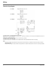
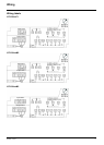
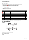
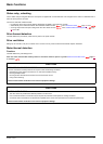
Electromagnetic compatibility (EMC)
Note: The high frequency equipotential ground connection between the drive, motor, and cable shielding does not eliminate the need to
connect the ground (PE) conductors (green-yellow) to the appropriate terminals on each unit. See Wiring recommendations on page 16
.
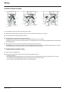
Principle and precautions
• Grounds between the drive, motor, and cable shielding must have high frequency equipotentiality.
• When using shielded cable for the motor, use a 4-conductor cable so that one wire will be the ground connection between the motor
and the drive. The size of the ground conductor must be selected in compliance with local and national codes. The shield can then
be grounded at both ends. Metal ducting or conduit can be used for part or all of the shielding length, provided there is no break in
continuity.
• When using shielded cable for Dynamic Brake (DB) resistors, use a 3-conductor cable so that one wire will be the ground connection
between the DB resistor assembly and the drive. The size of the ground conductor must be selected in compliance with local and
national codes. The shield can then be grounded at both ends. Metal ducting or conduit can be used for part or all of the shielding
length, provided there is no break in continuity.
• When using shielded cable for control signals, if the cable is connecting equipment that is close together and the grounds are bonded
together, then both ends of the shield can be grounded. If the cable is connected to equipment that may have a different ground
potential, then ground the shield at one end only to prevent large currents from flowing in the shield. The shield on the ungrounded
end may be tied to ground with a capacitor (for example: 10 nF, 100 V or higher) in order to provide a path for the higher frequency
noise. Keep the control circuits away from the power circuits. For control and speed reference circuits, we recommend using shielded
twisted cables with a pitch of between 25 and 50 mm (0.98 and 1.97 in.) Keep the control circuits away from the power circuits. For
control and speed reference circuits, we recommend using shielded twisted cables with a pitch of between 25 and 50 mm (0.98 and
1.97 in.)
• Ensure maximum separation between the power supply cable (line supply) and the motor cable.
• The motor cables must be at least 0.5 m (20 in.) long.
• Do not use surge arresters or power factor correction capacitors on the variable speed drive output.
• If using an additional input filter, it should be mounted as closed as possible to the drive and connected directly to the line supply via
an unshielded cable. Link 1 on the drive is via the filter output cable.
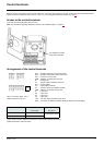
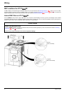
• For installation of the optional EMC plate and instructions for meeting IEC 61800-3 standard, refer to the section entitled “Installing
the EMC plates” and the instructions provided with the EMC plates.
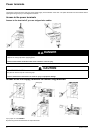
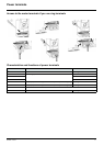
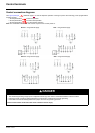
DANGER
HAZARD OF ELECTRIC SHOCK, EXPLOSION OR ARC FLASH
• Do not expose cable shielding except where connected to ground at the metal cable glands and underneath the grounding clamps.
• Ensure that there is no risk of the shielding coming into contact with live components.
Failure to follow these instructions will result in death or serious injury.