


BBV28581 05/2010 27
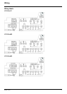
Wiring
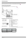
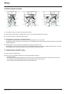
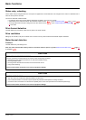
Installation diagram (example)
1. Non-shielded wires for the output of the status relay contacts.
2. Sheet steel grounded casing not supplied with the drive, to be mounted as indicated on the diagram.
3. PA and PC terminals, to the braking module DC bus
4. Shielded cable for connecting the control/signalling wiring.
For applications requiring several conductors, use small cross-sections (0.5 mm
2
, 20 AWG).
The shielding must be connected to ground at both ends. The shielding must be continuous and intermediate terminals must be in EMC
shielded metal boxes.
5. Shielded cable for motor connection with shielding connected to ground at both ends.
This shielding must be continuous, and if there are any intermediate terminals, these must be in an EMC shielded metal box. The motor
cable PE grounding conductor (green-yellow) must be connected to the grounded casing.
6. Grounding conductor, cross-section 10 mm²
(6 AWG) according to IEC 61800-5-1 standard.
7. Power input (non shielded cable)
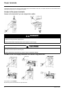
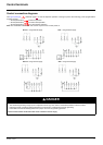
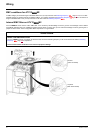
Attach and ground the shielding of cables 4 and 5 as close as possible to the drive:
• Expose the shielding.
• Use cable clamps of an appropriate size on the parts from which the shielding has been exposed, to attach them to the casing.
The shielding must be clamped tightly enough to the metal plate to ensure correct contact.
• Types of clamp: stainless steel (delivered with the optional EMC plate).