


32 BBV28581 05/2010
Programming
HMI description
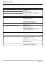
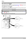
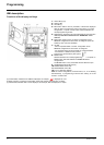
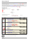
Functions of the display and keys
(a) If illuminated, indicates that a value is displayed, for example,
(b)When changing a value the Configuration mode LED and the value LED are on steady.
(c)If illuminated, indicates that a unit is displayed, for example, AMP is displayed for "Amps"
1. Value LED (a) (b).
2. Charge LED
3. Unit LED (c)
4. ESC button: Exits a menu or parameter, or aborts the displayed
value to return to the previous value in the memory. In LOCAL
configuration, 2 s press on ESC button switches between the
control/programming modes.
5. STOP button: stops the motor (could be hidden by door if function
disabled). Note: See instructions for "RUN/STOP" cover
removal.
6. RUN button: Starts running in LOCAL configuration and in
REMOTE configuration if the function is configured (could be
hidden by door if function disabled).
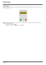
7. Jog dial
- Acts as a potentiometer in LOCAL configuration and in
REMOTE configuration if the function is configured.
- For navigation when turned clockwise or counterclockwise
- and selection / validation when pushed.
This action is represented by this symbol
8. MODE button
Switches between the control/programming modes. 3s press on
MODE button switches between the REMOTE/LOCAL
configurations.
The MODE button is only accessible with the HMI door open.
9. CONFIGURATION mode LED (b)
10. MONITORING mode LED
11. REFERENCE mode LED
12. Four "7-segment" displays
Note: In LOCAL configuration, the three Leds 9, 10, 11 are blinking
simultaneously in programming mode and are working as a Led
chaser in control mode.
5 is displayed for "0.5"0.