


18 BBV28581 05/2010
Wiring
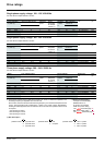
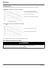
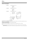
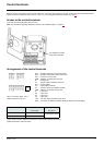
General wiring diagram
(1) R1 relay contacts, for remote indication of the drive status.
(2) Internal + 24 V
c. If an external source is used (+ 30 V c maximum), connect the 0 V of the source to the COM terminal, and do not
use the + 24 V
c terminal on the drive.
(3) Reference potentiometer SZ1RV1202 (2.2 k
Ω) or similar (10 kΩ maximum).
(4) Optional braking module VW3A7005
(5) Optional braking resistor VW3A7
ppp or other acceptable resistor. See the possible resistor values in the catalog.
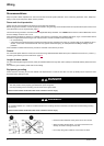
Note:
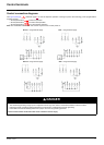
• Use transient voltage surge suppressors for all inductive circuits near the drive or coupled to the same circuit (relays, contactors,
solenoid valves, etc).
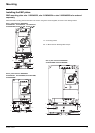
• The ground terminal (green screw) is located on the opposite side in comparison with its position on the ATV11 (see wiring trap label).
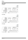
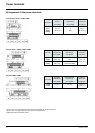
Single-phase supply 100...120 V
Three-phase supply 200...240 V
ATV12ppppF1
Single-phase supply 200...240 V
A
TV12ppppM2
A
TV12ppppM3
Source
3-phase
motor