


Multimeter Command Reference 111Chapter 3
OUTPut
The OUTPut command subsystem enables you to route the multimeter’s voltmeter
complete signal to the VXIbus TTL trigger lines.
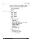
Subsystem Syntax OUTPut
:TTLTrg<
n>[:STATe] <mode>
:TTLTrg<
n>[:STATe]?
:TTLTrg[:STATe]
OUTPut:TTLTrg<n>[:STATe] <mode> enables or disables routing of the voltmeter
complete signal to the specified VXIbus trigger line (TTLTrg0 through TTLTrg7) on
the backplane P2 connector.
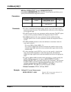
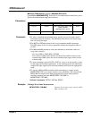
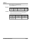
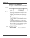
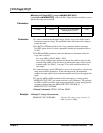
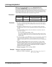
Parameters
Comments • You can substitute decimal values for the OFF (“0”) and ON (“1”) parameters.
• The voltmeter complete signal is always routed to the multimeter’s front panel
“VM Complete” BNC connector. When enabled (
ON), the OUTPut command
also routes voltmeter complete to the specified trigger line on connector P2.
When disabled (
OFF), voltmeter complete is routed only to the multimeter's
front panel connector.
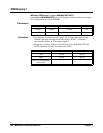
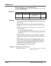
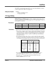
• The multimeter generates the voltmeter complete signal after it has sampled
the input for each reading. The length of time this low-going TTL signal is true
(low) depends on the aperture time and on the autozero mode as shown below.
• The VXIbus trigger lines are open-collector TTL lines that remain in a
non-asserted (high) state until the voltmeter complete signal is sent.
• More than one TTL output trigger line can be enabled at one time.
• *RST Condition: OUTP:TTLTn OFF
Parameter Name Parameter Type Range of Values Default Units
<n>
discrete 0|1|2|3|4|5|6|7 none
<mode>
boolean OFF|0|ON|1 none
Aperture Time Voltmeter Complete Low
Autozero ON Autozero OFF
320ms (50Hz) 350ms 350µs
267ms (60Hz) 370µs370µs
20ms (50Hz) 20.5ms 370µs
16.7ms (60Hz) 17.2ms 390µs
2.5ms (400Hz) 3.1ms 430µs
100µs520µs250µs
10µs70µs