


58 HP E1312A/E1412A Multimeter Application Information Chapter 2
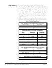
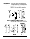
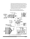
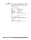
This example monitors the switch module’s status system. The switch
module’s status system (HP E1476A) is shown in Figure 2-4. This example
program enables the switch's “Scan Complete” bit to allow it to set the OPR
bit in the switch's status byte when the scan is finished. The program
repeatedly reads the switch module's status byte until the OPR bit gets set
which returns a status byte value of 128. This indicates the switch module
has completed all closures in the scan list. The multimeter's
FETC?
command causes the multimeter to transfer readings to the output buffer
after completing the last measurement. Readings are entered into the
computer using an I/O construct you provide.
Figure 2-4. HP E1476A Switch Module Status System
NOTE: This is the HP E1476A Switch Module’s status system.
See Figure 2-5 for the HP E1312A/E1412A Multimeter status system.