


HP E1312A/E1412A Multimeter Application Information 35Chapter 2
Low-Level
Measurement
Errors
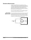
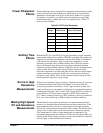
When measuring ac voltages less than 100mV, be aware that these
measurements are especially susceptible to errors introduced by extraneous
noise sources. Exposed (unshielded) cabling will act as an antenna and a
properly functioning multimeter will measure the signals received. The
entire measurement path, including the power line, acts as a loop antenna.
Circulating currents in the loop will create error voltages across any
impedances in series with the multimeter’s input. For this reason, you should
apply low-level ac voltages to the multimeter through shielded cables. You
should connect the shield to the input LO terminal.
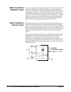
Make sure the multimeter and the ac source are connected to the same
electrical outlet whenever possible. You should also minimize the area of
any ground loops that cannot be avoided. Measurements of high-impedance
sources are more susceptible to noise pickup than measurements of low-
impedance sources. You can reduce the noise pick-up by placing a capacitor
in parallel with the multimeter’s input terminals. You may have to
experiment to determine the correct capacitor value for your application
since this capacitance will contribute some loading error.
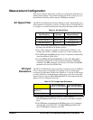
Most extraneous noise is not correlated with the input signal. You can
determine the error as shown below.
Correlated noise, while rare, is especially detrimental because it will always
add directly to the input signal. Measuring a low-level signal with the same
frequency as the local power line is a common situation prone to this error.
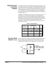
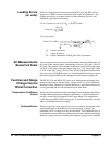
AC Turnover Errors Errors are generated when the multimeter’s input LO terminal is driven with
an ac voltage relative to earth. The most common situation where
unnecessary turnover errors are created is when the output of an ac calibrator
is connected to the multimeter “backwards.” Ideally, a multimeter reads the
same regardless of how the source is connected. Both source and multimeter
effects can degrade this ideal situation.
Because of the capacitance between the input LO terminal and earth
(approximately 200 pF for the HP E1312A and HP E1412A), the source will
experience different loading depending on how the input is applied. The
magnitude of the error is dependent upon the source's response to this
loading. The multimeter's measurement circuitry, while extensively
shielded, responds differently in the backward input case due to slight
differences in stray capacitance to earth. Because of this, the 100Vac and
300Vac ranges may latch up for high voltage, high frequency “backward”
inputs. Therefore, only drive the high terminal when measuring ac voltages.
You can use the grounding techniques described for dc common mode
problems to minimize ac common mode voltages (see Common Mode
Rejection (CMR) on page 27).
Voltage Measured = Vin
2
+ Noise
2