


HP E1312A/E1412A Multimeter Application Information 45Chapter 2
Triggering the Multimeter
This section discusses the multimeter’s trigger system and outlines the
different triggering configurations and programming methods used to
control the trigger system. Keep in mind that you do not have to program the
trigger system to make measurements. You can avoid having to learn the
information in this section by using the default trigger configuration set by
MEASure and CONFigure commands. However, you will need the
information in this section to take advantage of the flexibility of the
HP E1312A/E1412A trigger system when using the
CONFigure command.
The multimeter’s trigger system synchronizes measurements with specified
internal or external events. These events include software trigger commands,
negative-going edges on the VXIbus trigger lines (TTLT0 - TTLT7), and
negative-going pulses on the multimeter's external trigger (“Trig”) BNC
connector. The trigger system also allows you to specify the number of
triggers that will be accepted, the number of readings per trigger (sample
count), and the delay between the trigger and each reading.
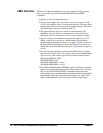
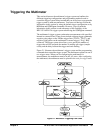
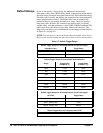
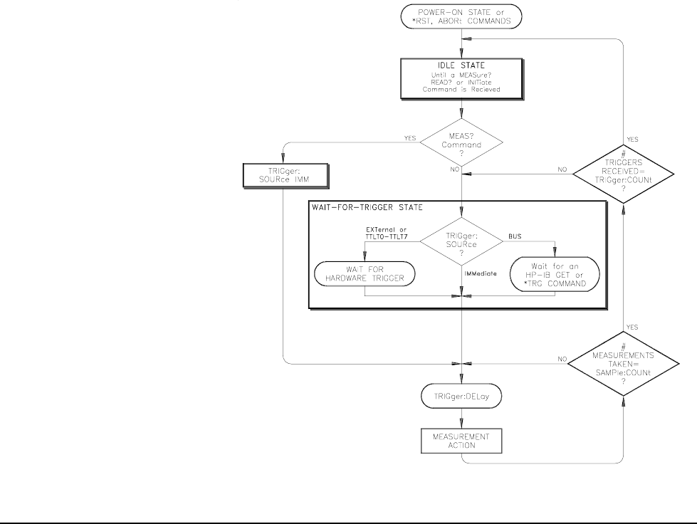
Figure 2-1 illustrates the multimeter's trigger system and the programming
commands that control the trigger system. The multimeter operates in one of
two trigger states. When you are configuring the multimeter for
measurements, the multimeter must be in the idle state. After configuring
the multimeter, the multimeter must be placed in the wait-for-trigger state.
Figure 2-1. Multimeter Triggering Flow Chart