


32 HP E1312A/E1412A Multimeter Application Information Chapter 2
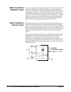
DC Current Measurement Errors
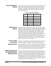
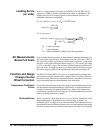
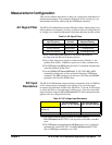
When you connect the multimeter in series with a test circuit to measure
current, a measurement error is introduced. The error is caused by the
multimeter’s series burden voltage. A voltage is developed across the wiring
resistance and current shunt resistance of the multimeter as shown below.
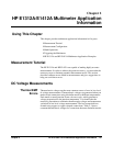
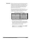
True RMS AC Measurements
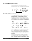
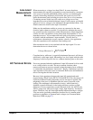
True RMS responding multimeters, like the HP E1312A and HP E1412A,
measure the “heating” potential of an applied signal. Unlike an “average
responding” measurement, a true
RMS measurement can be used to
determine the power dissipated in a resistance, even by non-sinusoidal
signals. The power is proportional to the square of the measured true
RMS
voltage, independent of waveshape. An average responding ac multimeter is
calibrated to read the same as a true
RMS meter for sinewave inputs only. For
other waveform shapes, an average responding meter will exhibit substantial
errors as shown below.
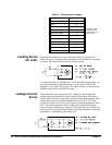
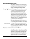
The multimeter's ac voltage and ac current functions measure the ac-coupled
true
RMS value. This is in contrast to the ac+dc true RMS value shown above.
Only the “heating value” of the ac components of the input waveform are
measured (dc is rejected). For non-offset sinewaves, triangle waves, and
square waves, the ac and ac+dc values are equal since these waveforms do
not contain a dc offset. Non-symmetrical waveforms, such as pulse trains,
contain dc voltages which are rejected by ac-coupled true
RMS
measurements.
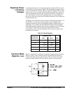
An ac-coupled true
RMS measurement is desirable in situations where you
are measuring small ac signals in the presence of large dc offsets such as
when measuring ac ripple present on dc power supplies. There are situations,
however, where you might want to know the ac+dc true
RMS value. You can