


ATM and VLAN Management Maps 1-7
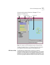
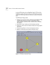
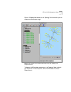
the branch and then select the Zoom icon. See page 1-27 for a
description of the Zoom icon.
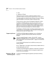
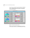
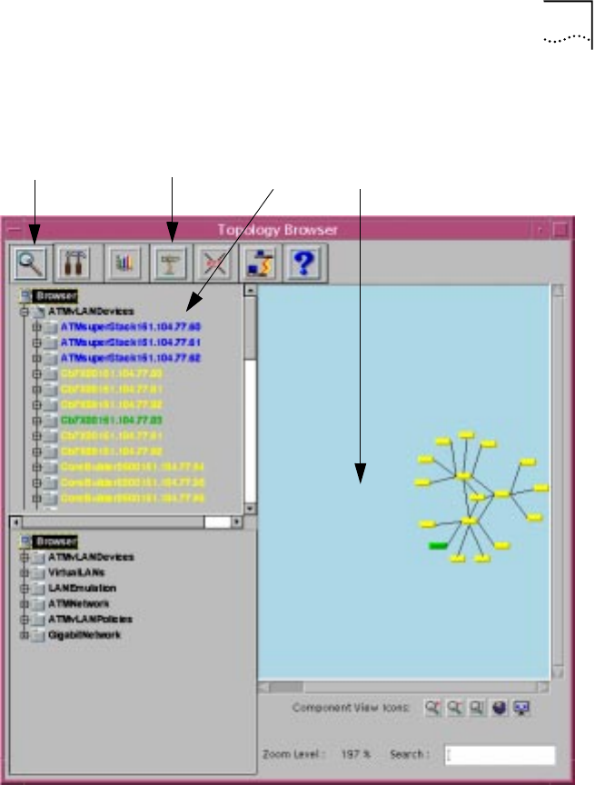
Figure 1-3 Access to the ATM Devices Map through the Topology Browser
To display the selected device in the Topology View, select the device in
the Component View and then select the Cross Reference icon.
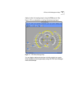
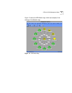
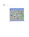
ATM Network Map The ATM Network map (see Figure 1-4) allows you to perform
management tasks on different ATM devices,depending on their physical
connectivity. The ATM Network window displays a hierarchical switching
backbone of the network. Each icon represents a switching domain, such
as a central high-speed CoreBuilder ATM switch module that is connected
Zoom icon Topology View
Zoom icon
Cross Reference icon
Component View