


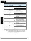

“C” Group: Intelligent Terminal Functions
Configuring
Drive Parameters
3–46
Note 1: When using the Multi-speed Select settings CF1 to CF4, do not display
parameter F001 or change the value of F001 while the inverter is in Run Mode
(motor running). If it is necessary to check the value of F001 during Run
Mode, please monitor D001 instead of F001.
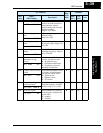
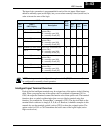
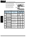
24 PIDC PID Reset ON Resets the PID loop controller. The main conse-
quence is that the integrator sum is forced to
zero.
OFF No effect on PID loop controller
27 UP Remote Control
UP Function (motor-
ized speed pot.)
ON Accelerates (increases output frequency) motor
from current frequency
OFF Output to motor operates normally
28 DWN Remote Control
DOWN Function
(motorized speed
pot.)
ON Decelerates (decreases output frequency) motor
from current frequency
OFF Output to motor operates normally
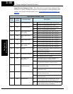
29 UDC Remote Control Data
Clearing
ON Clears the UP/DWN frequency memory by
forcing it to equal the set frequency parameter
F001. Setting C101 must be set=00 to enable this
function to work.
OFF UP/DWN frequency memory is not changed
31 OPE Operator Control ON Forces the source of the output frequency setting
(A001) and the source of the RUN command
(A002) to be from the digital operator
OFF Source of output frequency set by (A001) and
source of run command set by (A002) is used
50 ADD ADD frequency
enable
ON Adds the A145 value (Add Frequency) to the
output frequency
OFF Does not add the A145 value to the output
frequency
51 F-TM Force Terminal
Mode
ON Force inverter to use input terminals for output
frequency and Run command sources
OFF Source of output frequency set by (A001) and
source of Run command set by (A002) is used
255
—
Not selected ON (input ignored)
OFF (input ignored)
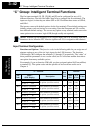
Input Function Summary Table
Option
Code
Terminal
Symbol
Function Name Description