


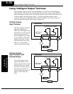
Using Intelligent Input Terminals
Operations
and Monitoring
4–30
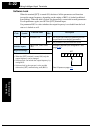
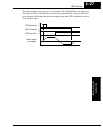
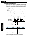
It is possible for the inverter to retain the frequency set from the [UP] and [DWN] termi-
nals through a power loss. Parameter C101 enables/disables the memory. If disabled, the
inverter retains the last frequency before an UP/DWN adjustment. Use the [UDC]
terminal to clear the memory and return to the original set output frequency.
Option
Code
Terminal
Symbol
Function Name
Input
State
Description
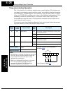
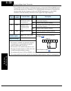
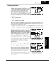
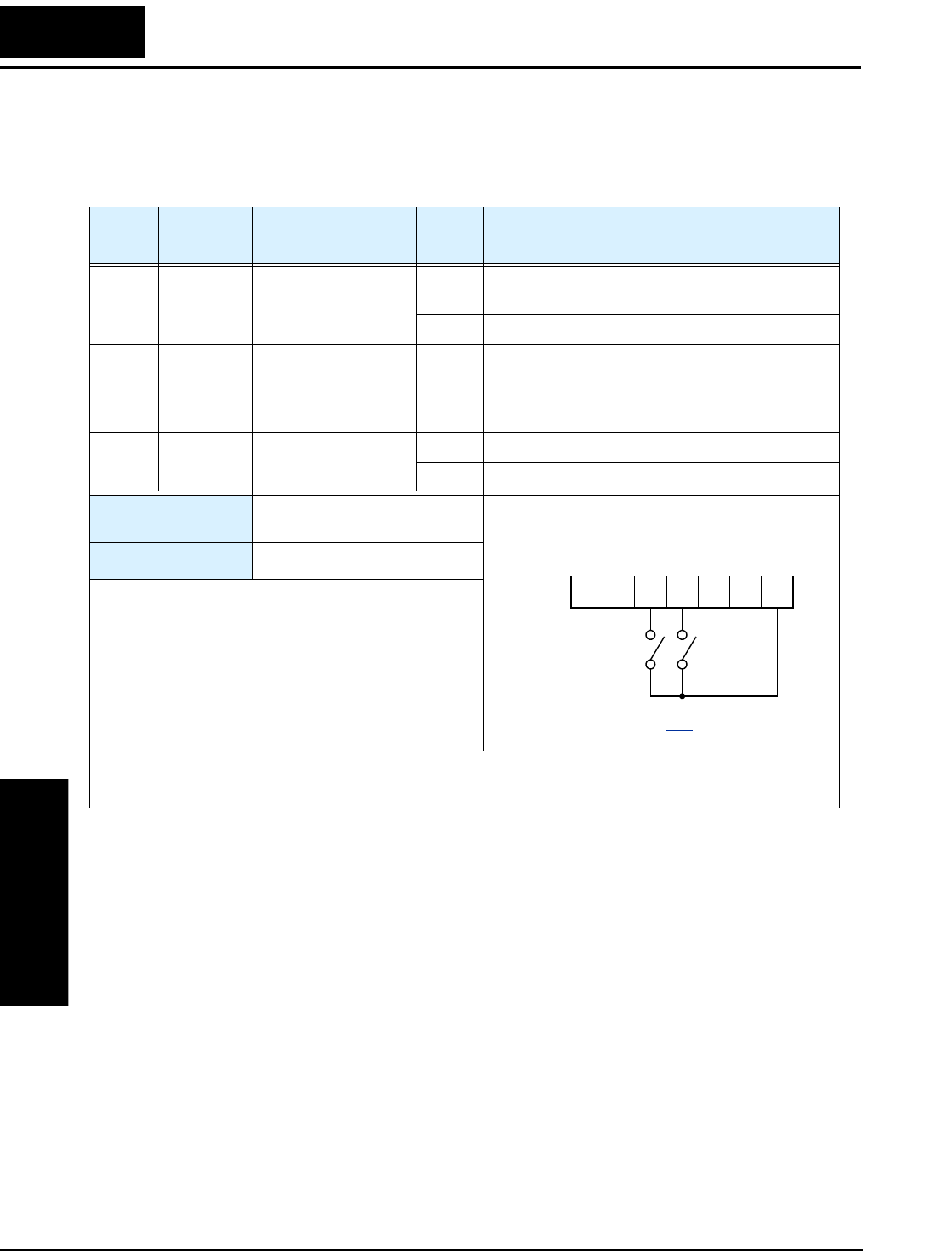
27 UP Remote Control
UP Function (motor-
ized speed pot.)
ON Accelerates (increases output frequency) motor
from current frequency
OFF Output to motor operates normally
28 DWN Remote Control
DOWN Function
(motorized speed
pot.)
ON Decelerates (decreases output frequency) motor
from current frequency
OFF Output to motor operates normally
29 UDC Remote Control Data
Clear
ON Clears the Up/down frequency memory
OFF
No effect on Up/down memory
Valid for inputs:
C001, C002, C003, C004,
C005
Required settings:
A001 = 02
Notes:
•
This feature is available only when the frequency
command source is programmed for operator
control. Confirm A001 is set to 02.
• This function is not available when [JG] is in use.
• The range of output frequency is 0 Hz to the value
in A004 (maximum frequency setting).
• The minimum ON time of [UP] and [DWN] is 50 ms.
• This setting modifies the inverter speed from using F001 output frequency setting as a starting point.
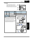
Example (requires input configuration—
see page 3–42
):
See I/O specs on page 4–6
.
DWN UP
12345L
PCS