


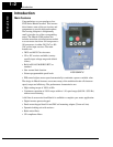
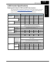
L200 Inverter Specifications
Getting Started
1–10
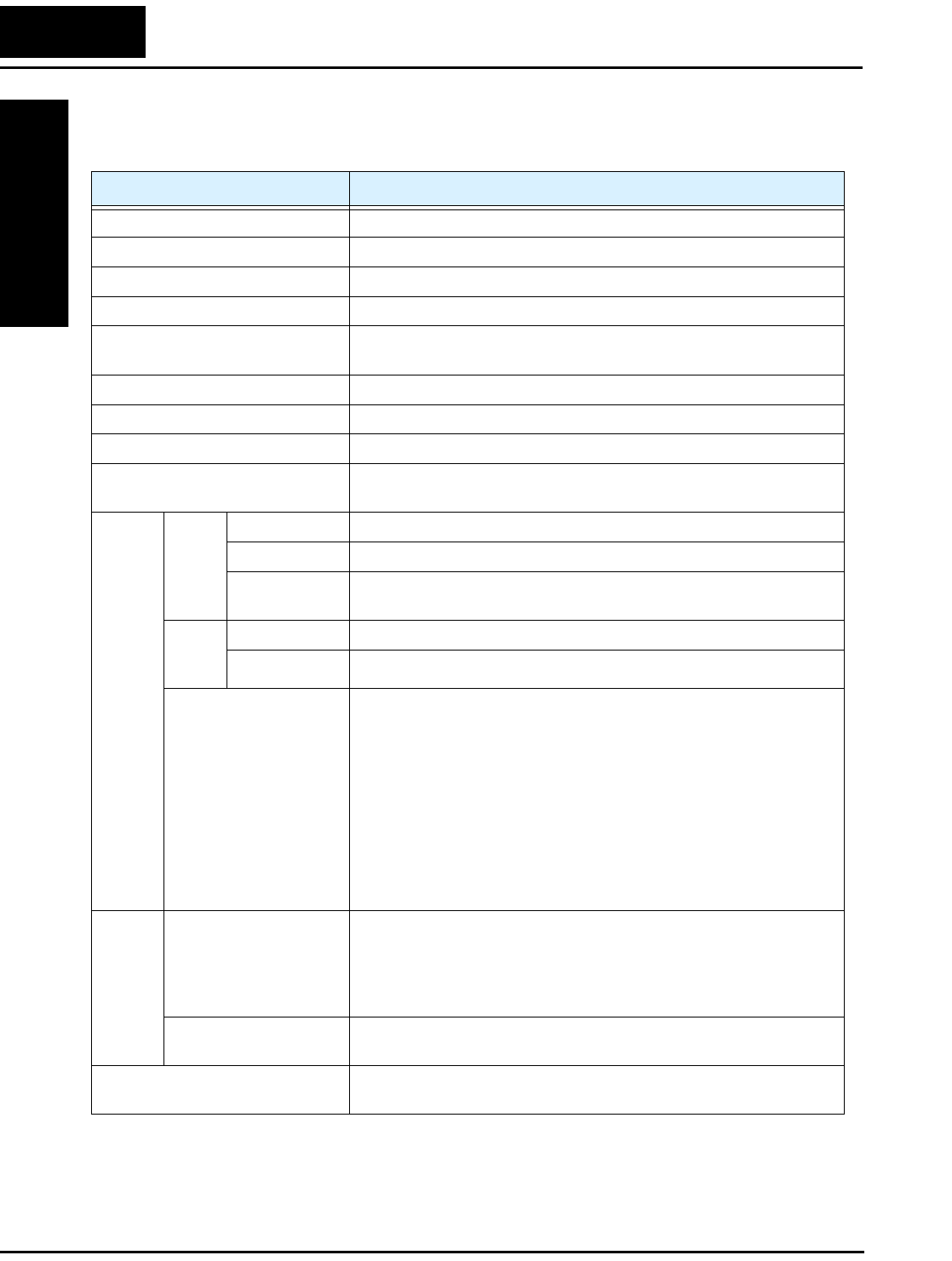
General Specifications
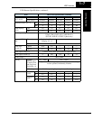
The following table applies to all L200 inverters.
Item General Specifications
Protective housing *1 IP20
Control method Sinusoidal Pulse Width Modulation (PWM) control
Carrier frequency 2kHz to 14kHz (default setting: 5kHz)
Output frequency range *4 0.5 to 400 Hz
Frequency accuracy Digital command: 0.01% of the maximum frequency
Analog command: 0.1% of the maximum frequency (25°C ± 10°C)
Frequency setting resolution Digital: 0.1 Hz; Analog: max. frequency/1000
Volt./Freq. characteristic V/f optionally variable, V/f control (constant torque, reduced torque)
Overload capacity 150% of rated current for 1 minute
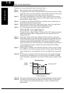
Acceleration/deceleration time 0.01 to 3000 seconds, linear and S-curve accel/decel, second
accel/decel setting available
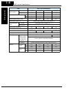
Input
signal
Freq.
setting
Operator panel Up and Down keys / Value settings
Potentiometer Analog setting
External signal
*9
0 to 10 VDC (input impedance 10k Ohms), 4 to 20 mA (input
impedance 250 Ohms), Potentiometer (1k to 2k Ohms, 2W)
FWD/
REV
Run
Operator panel Run/Stop (Forward/Reverse run change by command)
External signal Forward run/stop, Reverse run/stop
Intelligent input
terminal
FW (forward run command), RV (reverse run command), CF1~CF4
(multi-stage speed setting), JG (jog command), DB (external
braking), SET (set second motor), 2CH (2-stage accel./decel.
command), FRS (free run stop command), EXT (external trip), USP
(startup function), SFT (soft lock), AT (analog current input select
signal), RS (reset), TH (thermistor thermal protection), STA (start),
STP (stop), F/R (forward/reverse), PID (PID disable), PIDC (PID
reset), UP (remote control up function), DWN (remote control down
function), UDC (remote control data clearing), OPE (operator
control), ADD (ADD frequency enable), F-TM (force terminal
mode)
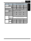
Output
signal
Intelligent output
terminal
RUN (run status signal), FA1,2 (frequency arrival signal), OL
(overload advance notice signal), OD (PID error deviation signal),
AL (alarm signal), Dc (analog input disconnect detect), FBV (PID
two-stage control output), NDc (network detection signal), LOG
(logic output)
Frequency monitor PWM output; Select analog output frequency monitor, analog output
current monitor or digital output frequency monitor
Alarm output contact ON for inverter alarm (1C contacts, both normally open or closed
avail.)