


Using Intelligent Output Terminals
Operations
and Monitoring
4–34
Using Intelligent Output Terminals
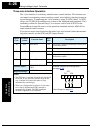
The intelligent output terminals are programmable in a similar way to the intelligent
input terminals. The inverter has several output functions that you can assign individu-
ally to three physical logic outputs. Two of the outputs are open-collector transistors, and
the third output is the alarm relay (form C – normally open and normally closed
contacts). The relay is assigned the alarm function by default, but you can assign it to
any of the functions that the open-collector outputs use.
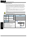
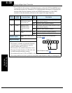
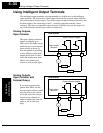
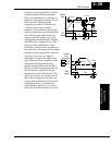
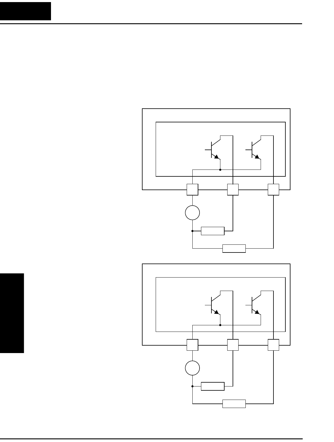
Sinking Outputs,
Open Collector
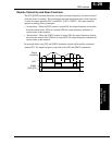
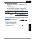
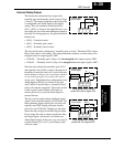
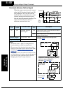
Sinking Outputs,
Open Collector with
External Relays
L200 Inverter
12 11
CM2
Open collector outputs
Load
Load
–
+
Logic output
common
The open-collector transistor
outputs can handle up to
50mA each. We highly recom-
mend that you use an external
power source as shown. It
must be capable of providing
at least 100mA to drive both
outputs at full load. To drive
loads that require more than
50mA, use external relay
circuits as shown to the right.
L200 Inverter
12 11
CM2
Open collector outputs
Load
Load
–
+
Logic output
common
If you need output current
greater than 50mA, use the
inverter output to drive a small
relay. Be sure to use a diode
across the coil of the relay as
shown (reverse-biased) in
order to suppress the turn-off
spike, or use a solid-state
relay.