


ModBus Data Listing
Appendix B
B–36
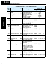
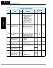
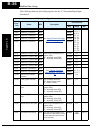
The following table lists the holding registers for the “C” Group Intelligent Input
Functions.
I
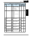
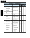
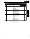
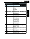
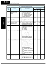
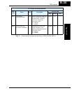
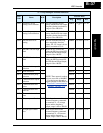
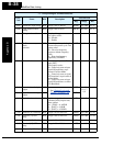
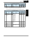
“C” Group Intelligent Terminal Functions
Func.
Code
Name R/W Description
Network Data
Reg. Range Res.
C001 Terminal [1] function R/W
See
“Input Terminal Config-
uration” on page 3–42
00A7h 0, 1, 2, 3,
4, 5, 6, 7,
8, 9, 11,
12, 13,
15, 16,
18, 19,
20, 21,
22, 23,
24, 27,
28, 29,
31, 50,
51, 255
—
C002 Terminal [2] function R/W 00A8h
C003 Terminal [3] function R/W 00A9h
C004 Terminal [4] function R/W 00AAh
C005 Terminal [5] function R/W 00ABh
C011 Terminal [1] active state R/W Select logic convention, two
option codes:
00...normally open [NO]
01...normally closed [NC]
00ADh 0, 1 —
C012 Terminal [2] active state R/W 00AEh 0, 1 —
C013 Terminal [3] active state R/W 00AFh 0, 1 —
C014 Terminal [4] active state R/W 00B0h 0, 1 —
C015 Terminal [5] active state R/W 00B1h 0, 1 —
C021 Terminal [11] function R/W
See
“Output Terminal
Configuration” on page 3–
47
00B3h
0, 1, 2, 3,
4, 5, 6, 7,
8, 9
—
C022 Terminal [12] function R/W 00B4h
C026 Alarm relay terminal
function
R/W 00B5h
C028 [AM] signal selection R/W Two available functions:
00...Actual motor speed
01...Motor current
00B7h 0, 1 —
C031 Terminal [11] active
state
R/W Select logic convention, two
option codes:
00...normally open (NO)
01...normally closed (NC)
00B8h 0, 1 —
C032 Terminal [12] active
state
R/W Select logic convention, two
option codes:
00...normally open (NO)
01...normally closed (NC)
00B9h 0, 1 —
C036 Alarm relay active state R/W Select logic convention, two
option codes:
00...normally open (NO)
01...normally closed (NC)
00BAh 0, 1 —
C041 Overload level setting R/W Sets the overload signal level
between 0% and 200% (from 0
to two times the rated current
of the inverter)
00BBh 0 to
20000
0.01 %