


L200 Inverter
Configuring
Drive Parameters
3–51
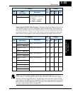
Network Communication Settings
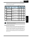
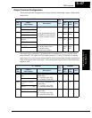
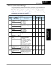
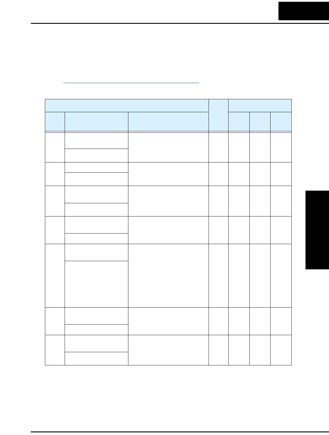
The following table lists parameters that configure the inverter’s serial communications
port. The settings affect how the inverter communicates with a digital operator (such as
SRW–0EX), as well as a ModBus network (for networked inverter applications). The
settings cannot be edited via the network, in order to ensure network reliability. Refer to
“
ModBus Network Communications” on page B–1 for more information on controlling
and monitoring your inverter from a network.
“C” Function
Run
Mode
Edit
Defaults
Func.
Code
Name /
SRW Display
Description
–FEF
(EU)
–FU
(USA)
Units
C071 Communication speed
selection
Three option codes:
04...4800 bps
05...9600 bps
06...19200 bps
✘ 06 04 baud
COM BAU 4800
C072 Node allocation Set the address of the inverter
on the network. Range is 1 to
32.
✘ 1.
.1
—
COM ADR 00001
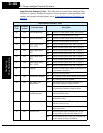
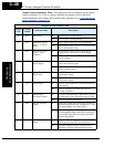
C074 Communication parity
selection
Three option codes:
00...No parity
01...Even parity
02...Odd parity
✘ 00
00
—
COM PRTY NON
C075 Communication stop bit
selection
Range is 1 to 2 ✘ 1
1
—
COM STP 1BIT
C076 Communication error
select
Selects inverter response to
communications error.
Five options:
00...Trip (error code E60)
01...Decelerate to a stop and
trip (error code E60)
02...Disable
03...Free run stop (coasting)
04...Decelerate to a stop
✘ 02
02
—
COM ESlct None
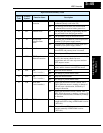
C077 Communication error
time-out
Sets the communications
watchdog timer period.
Range is 0.00 to 99.99 sec.
✘ 0.00 0.00 sec.
COM ETIM 000.00s
C078 Communication wait
time
Time the inverter waits after
receiving a message before it
transmits.
Range is 0. to 1000. ms
✘ 0.
0.
msec.
COM Wait 00000ms