


Step-by-Step Basic Installation
Inverter Mounting
and Installation
2–20
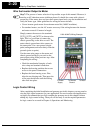
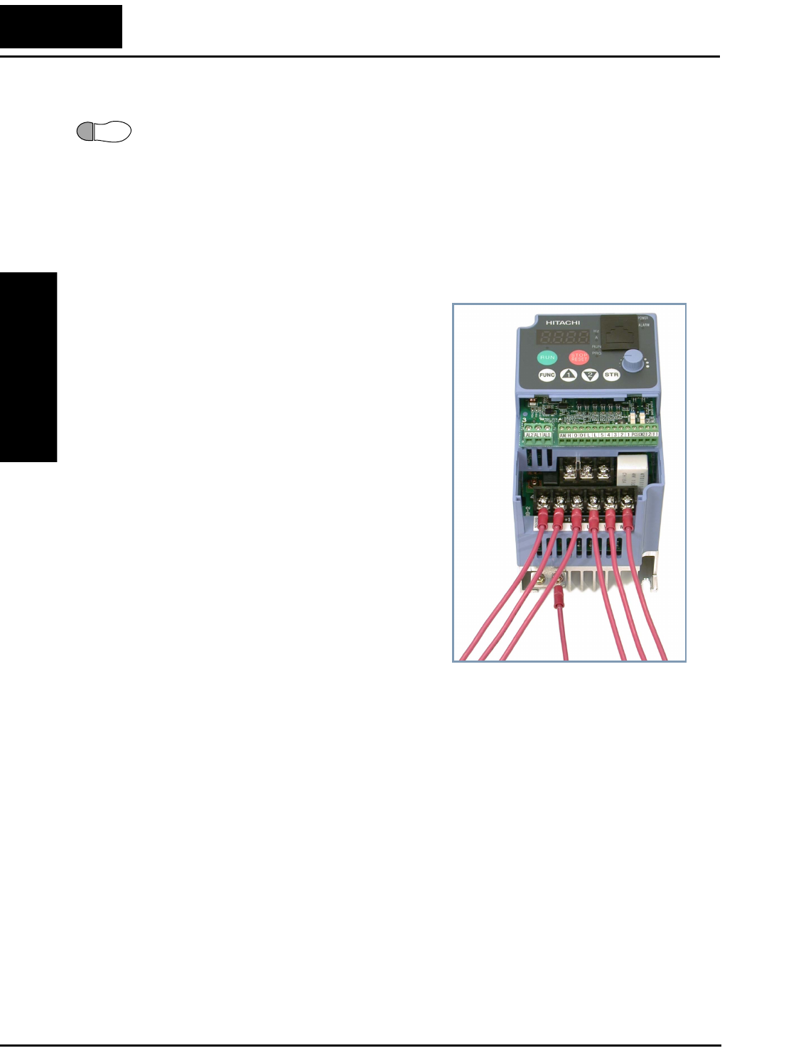
Wire the Inverter Output to Motor
Step 7: The process of motor selection is beyond the scope of this manual. However, it
must be an AC induction motor with three phases. It should also come with a chassis
ground lug. If the motor does not have three power input leads, stop the installation and
verify the motor type. Other guidelines for wiring the motor include:
• Use an inverter-grade motor for maximum motor life (1600V insulation).
• For standard motors, use the AC reactor accessory if the wiring between the inverter
and motor exceeds 10 meters in length.
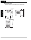
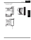
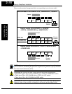
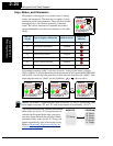
Simply connect the motor to the terminals
[U/T1], [V/T2], and [W/T3] as shown to the
right. This is a good time to connect the
chassis ground lug on the drive as well. The
motor chassis ground must also connect to
the same point. Use a star ground (single-
point) arrangement, and never daisy-chain the
grounds (point-to-point).
Use the same wire gauge on the motor and
chassis ground wiring as you used on the
power input wiring in the previous step. After
completing the wiring:
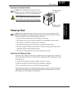
• Check the mechanical integrity of each
wire crimp and terminal connection.
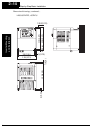
• Replace the housing partition that covers
access to the power connections.
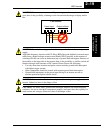
• Replace the front housing cover. First,
align the two hinging tabs. Then press the
cover onto the inverter until the locking
tabs click into place.
Logic Control Wiring
After completing the initial installation and powerup test in this chapter, you may need to
wire the logic signal connector for your application. For new inverter users/applications,
we highly recommend that you first complete the powerup test in this chapter without
adding any logic control wiring. Then you will be ready to set the required parameters
for logic control as covered in Chapter 4, Operations and Monitoring.
7
To Power
Supply
To MotorTo Chassis
Ground
L200–004NFU Wiring Example