


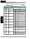
“C” Group: Intelligent Terminal Functions
Configuring
Drive Parameters
3–54
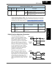
Output Logic and Timing
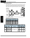
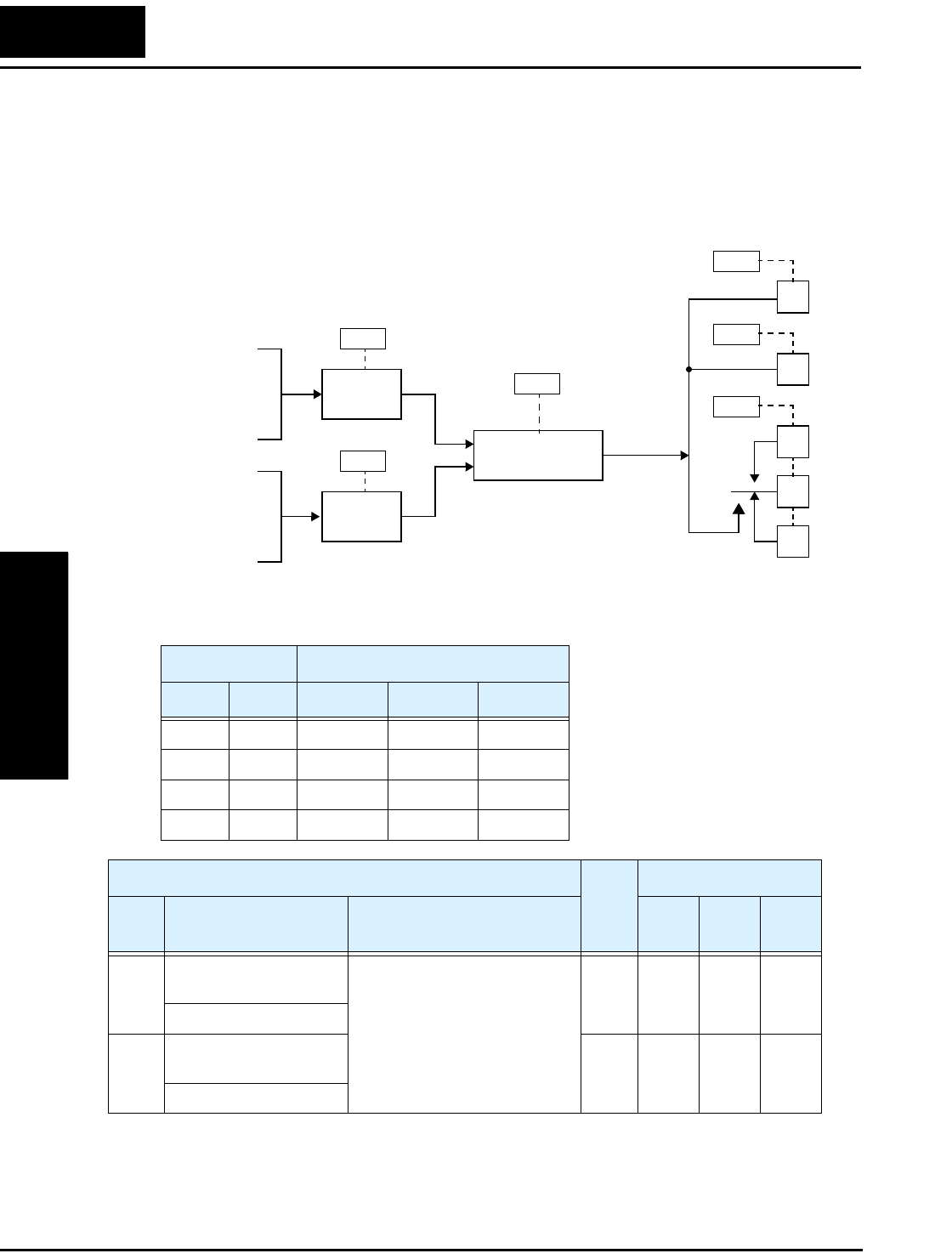
Logic Output Function – The inverter has a built-in logic output feature. You can select
any two of the other nine intelligent output options for internal inputs. Then, configure
the logic function to apply the logical AND, OR, or XOR (exclusive OR) operator as
desired to the two inputs. The terminal symbol for the new output is [LOG]. Use C021,
C022, or C026 to route the logical result to terminal [11], [12], or the relay terminals.
The following table shows all four possible logic input combinations with each of the
three available logical operations.
Input States [LOG] Output State
A B AND OR XOR
00000
01011
10011
11110
C141
Logic function
AND, OR, XOR
Input A
RUN, FA1,
FA2, OL,
OD, AL, Dc,
FBV, NDc
Intelligent out-
puts used as
internal inputs:
C142
Input B
RUN, FA1,
FA2, OL,
OD, AL, Dc,
FBV, NDc
C143
12
11
AL1
AL0
AL2
C021
C022
C026
[LOG]
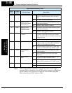
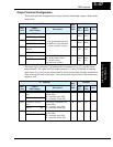
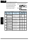
“C” Function
Run
Mode
Edit
Defaults
Func.
Code
Name /
SRW Display
Description
–FEF
(EU)
–FU
(USA)
Units
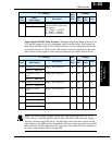
C141 Input A select for logic
output
9 programmable functions
available for logic (discrete)
outputs
✘ 00 00 —
LogicOut1 RUN
C142 Input B select for logic
output
✘ 01 01 —
LogicOut2 FA1