


L200 Inverter
Configuring
Drive Parameters
3–23
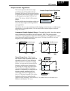
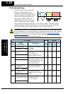
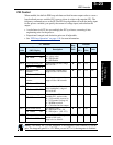
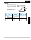
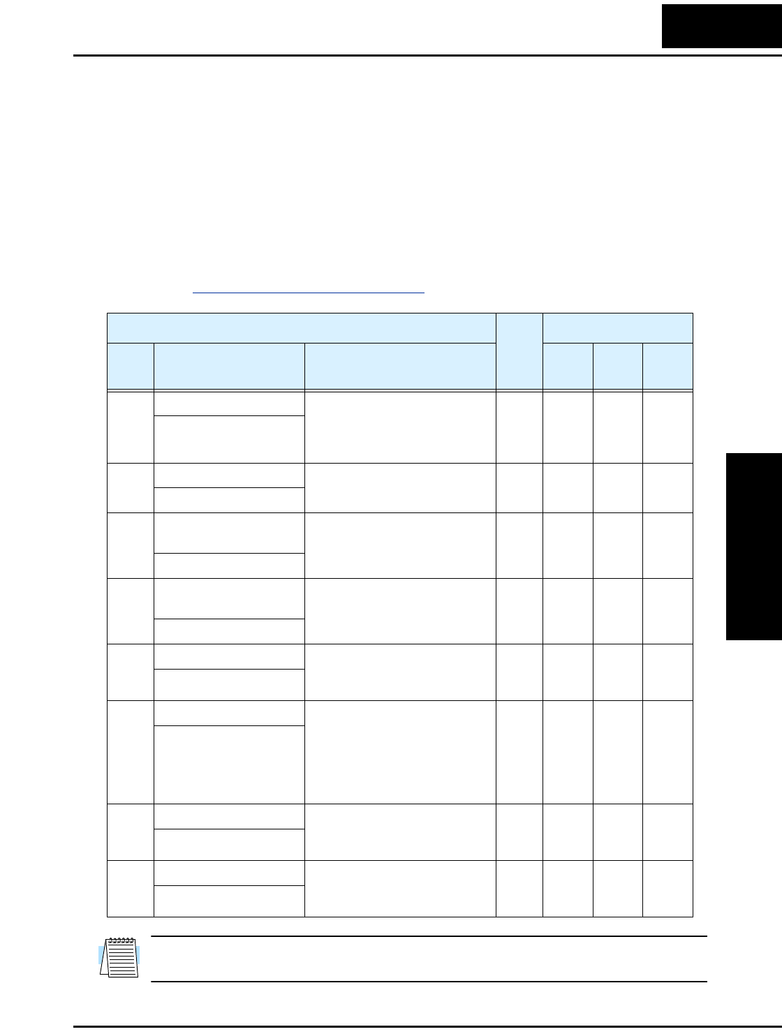
PID Control
When enabled, the built-in PID loop calculates an ideal inverter output value to cause a
loop feedback process variable (PV) to move closer in value to the setpoint (SP). The
frequency command serves as the SP. The PID loop algorithm will read the analog input
for the process variable (you specify the current or voltage input) and calculate the
output.
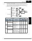
• A scale factor in A075 lets you multiply the PV by a factor, converting it into
engineering units for the process.
• Proportional, integral, and derivative gains are all adjustable.
• See “
PID Loop Operation” on page 4–54 for more information.
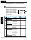
NOTE: The setting A073 for the integrator is the integrator’s time constant Ti, not the
gain. The integrator gain Ki = 1/Ti. When you set A073 = 0, the integrator is disabled.
“A” Function
Run
Mode
Edit
Defaults
Func.
Code
Name /
SRW Display
Description
–FEF
(EU)
–FU
(USA)
Units
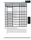
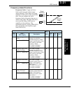
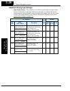
A071 PID Enable Enables PID function,
two option codes:
00...PID Disable
01...PID Enable
✘ 00 00 —
PID Mode OFF
A072 PID proportional gain Proportional gain has a range
of 0.2 to 5.0
✔ 1.0 1.0 —
PID P 0001.0
A073 PID integral time
constant
Integral time constant has a
range of 0.0 to 150 seconds
✔ 1.0 1.0 sec.
PID I 0001.0s
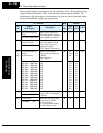
A074 PID derivative time
constant
Derivative time constant has a
range of 0.0 to 100 seconds
✔ 0.0 0.0 sec.
PID D 000.00s
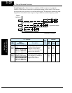
A075 PV scale conversion Process Variable (PV) scale
factor (multiplier), range of
0.01 to 99.99
✘ 1.00 1.00 —
PID Cnv 001.00%
A076 PV source setting Selects source of Process
Variable (PV), option codes:
00...[OI] terminal (current in)
01...[O] terminal (voltage in)
02...ModBus network
03...Calculate function output
✘ 00 00 —
PID INP OI
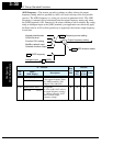
A077 Reverse PID action Two option codes:
00...PID input = SP – PV
01...PID input = –(SP – PV)
✘ 00 00 —
PID MINUS OFF
A078 PID output limit Sets the limit of PID output as
percent of full scale,
range is 0.0 to 100.0%
✘ 0.0 0.0 %
PID Vari 0000.0%