


“D” Group: Monitoring Functions
Configuring
Drive Parameters
3–6
“D” Group: Monitoring Functions
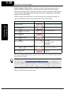
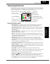
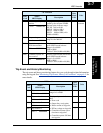
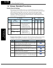
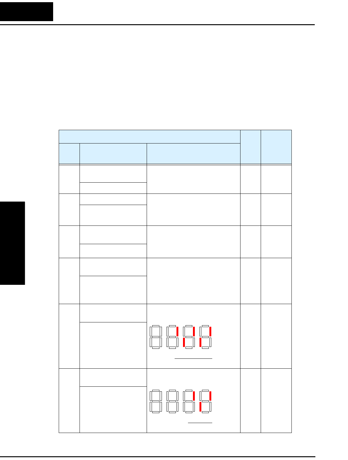
You can access important system parameter values with the “D” Group monitoring
functions, whether the inverter is in Run Mode or Stop Mode. After selecting the
function code number for the parameter you want to monitor, press the Function key
once to show the value on the display. In functions D005 and D006, the intelligent termi-
nals use individual segments of the display to show ON/OFF status.
If the inverter display is set to monitor a parameter and powerdown occurs, the inverter
stores the present monitor function setting. For your convenience, the display automati-
cally returns to the previously monitored parameter upon the next powerup.
“D” Function
Run
Mode
Edit
Units
Func.
Code
Name /
SRW Display
Description
D001 Output frequency
monitor
Real-time display of output
frequency to motor, from
0.0 to 400.0 Hz
—Hz
FM 0000.00Hz
D002 Output current monitor Filtered display of output current
to motor (100 ms internal filter
time constant), range is
0 to 200% of inverter rated current
—A
Iout 0000.0A
D003 Rotation direction
monitor
Three different indications:
“F”..... Forward
“o” .. Stop
“r”..... Reverse
——
Dir STOP
D004 Process variable (PV),
PID feedback monitor
Displays the scaled PID process
variable (feedback) value (A075 is
scale factor),
0.00 to 99.99, 100.0 to 999.9,
1000. to 9999., 1000 to 999,
and 10000 to 99900
— % times
constant
FB 00000.00%
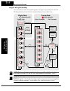
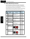
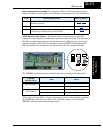
D005 Intelligent input
terminal status
Displays the state of the intelligent
input terminals:
——
IN-TM LLLLL
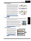
D006 Intelligent output
terminal status
Displays the state of the intelligent
output terminals:
——
OUT-TM LLL
ON
OFF
12345
Terminal numbers
ON
OFF
1112
Terminal numbers
AL