


L200 Inverter
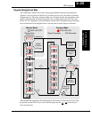
Inverter Mounting
and Installation
2–29
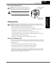
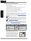
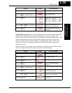
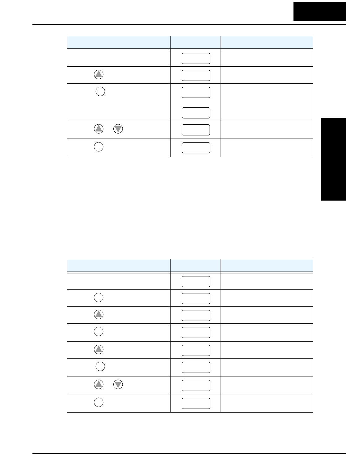
Set the Motor Current - The inverter has thermal overload protection that is designed
to protect the inverter and motor from overheating due to an excessive load. The
inverter’s uses the motor’s current rating to calculate the time-based heating effect. This
protection depends on using the correct current rating for your motor. The level of
electronic thermal setting, parameter B012, is adjustable from 20% to 120% of the
inverter’s rated current. A proper configuration will also help prevent unnecessary
inverter trip events.
Read the motor’s current rating on its manufacturer’s nameplate. Then follow the steps
below to configure the inverter’s thermal overload protection setting.
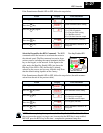
Action Display Func./Parameter
(Starting point)
Base frequency setting
Press the
key and hold until-->
AVR voltage select
Press the key.
or
Default values for AVR voltage:
200V class = 230VAC
400V class = 400VAC (–xxxFEF)
400V class = 460VAC (–xxxFU)
Press the
or key as needed.
Set to your motor specs (your
display may be different)
Press the
key.
Stores parameter, returns to “A”
Group list
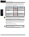
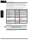
Action Display Func./Parameter
(Starting point)
Base frequency setting
Press the
key.
“A” Group selected
Press the
key.
“B” Group selected
Press the
key.
First “B” Group parameter
selected
Press the
key and hold until-->
Level of electronic thermal setting
Press the key.
Default value will be 100% of
inverter rated current.
Press the
or key as needed.
Set to your motor specs (your
display may be different)
Press the
key.
Stores parameter, returns to “B”
Group list
A003
1
A082
FUNC.
230
400
1
2
21 5
STR
A082
A082
FUNC.
A– – –
1
b
–––
FUNC.
b
001
1
b
01 2
FUNC.
1.60
1
2
1.80
STR
B01 2