


L200 Inverter
Configuring
Drive Parameters
3–15
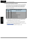
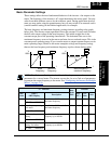
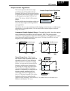
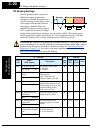
Multi-speed and Jog Frequency Setting
The L200 inverter has the capability to store and output up to 16 preset frequencies to the
motor (A020 to A035). As in traditional motion terminology, we call this multi-speed
profile capability. These preset frequencies are selected by means of digital inputs to the
inverter. The inverter applies the current acceleration or deceleration setting to change
from the current output frequency to the new one. The first multi-speed setting is dupli-
cated for the second motor settings (the remaining 15 multi-speeds apply only to the first
motor).
“A” Function
Run
Mode
Edit
Defaults
Func.
Code
Name /
SRW Display
Description
–FEF
(EU)
–FU
(USA)
Units
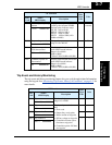
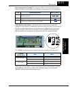
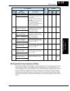
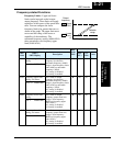
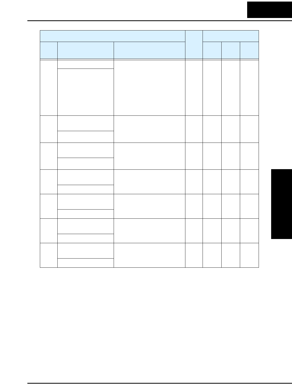
A005 [AT] selection Four options, select codes:
00...Select between [O] and
[OI] at [AT]
01...[O] + [OI] ([AT] input is
ignored)
02...Select between [O] and
keypad potentiometer
03...Select between [OI] and
keypad potentiometer
✘ 00 00 Hz
AT-Slct O/OI
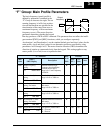
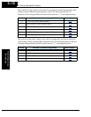
A011 Pot./O–L input active
range start frequency
The output frequency corre-
sponding to the analog input
range starting point,
range is 0.0 to 400.0
✘ 0.0 0.0 Hz
O-EXS 0000.0Hz
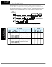
A012 Pot./O–L input active
range end frequency
The output frequency corre-
sponding to the analog input
range ending point,
range is 0.0 to 400.0
✘ 0.0 0.0 Hz
O-EXE 0000.0Hz
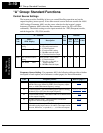
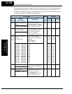
A013 Pot./O–L input active
range start voltage
The starting point (offset) for
the active analog input range,
range is 0. to 100.
✘ 0. 0. %
O-EX%S 00000%
A014 Pot./O–L input active
range end voltage
The ending point (offset) for
the active analog input range,
range is 0. to 100.
✘ 100. 100. %
O-EX%E 00100%
A015 Pot./O–L input start
frequency enable
Two options; select codes:
00...Use offset (A011 value)
01...Use 0 Hz
✘ 01 01 —
O-LVL 0Hz
A016 External frequency
filter time constant
Range n = 1 to 8, where n =
number of samples for avg.
✘ 2. 8. Sam-
ples
F-SAMP 00008