


Step-by-Step Basic Installation
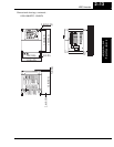
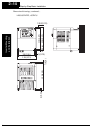
Inverter Mounting
and Installation
2–8
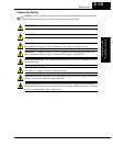
WARNING: In the cases below involving a general-purpose inverter, a large peak
current can flow on the power supply side, sometimes destroying the converter module:
1.The unbalance factor of the power supply is 3% or higher.
2.The power supply capacity is at least 10 times greater than the inverter capacity
(or the power supply capacity is 500 kVA or more).
3.Abrupt power supply changes are expected, due to conditions such as:
a. Several inverters are interconnected with a short bus.
b. A thyristor converter and an inverter are interconnected with a short bus.
c. An installed phase advance capacitor opens and closes.
Where these conditions exist or when the connected equipment must be highly reliable,
you MUST install an input-side AC reactor of 3% (at a voltage drop at rated current)
with respect to the supply voltage on the power supply side. Also, where the effects of an
indirect lightning strike are possible, install a lightning conductor.
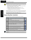
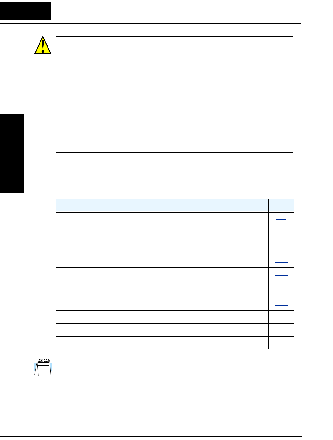
Step-by-Step Basic Installation
This section will guide you through the following basic steps of installation:
NOTE: If the installation is in an EU country, study the EMC installation guidelines in
Appendix D.
Step Activity Page
1
Choose a mounting location in compliance with the Warnings and Cautions.
See NOTE below.
2–9
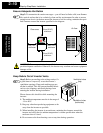
2
Check the mounting location for adequate ventilation.
2–10
3
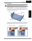
Cover the inverter’s ventilation openings to prevent debris from entering.
2–10
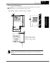
4
Check the inverter dimensions for footprint and mounting hole locations.
2–11
5
Study the Cautions, Warnings, wire and fuse sizes, and terminal torque
specifications before wiring the inverter.
2–15
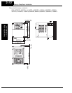
6
Connect wiring for the inverter power input.
2–17
7
Wire the inverter output to the motor.
2–20
8
Uncover the inverter’s ventilation openings applied in Step 3.
2–21
9
Perform the Powerup Test. (This step includes several substeps.)
2–21
10
Make observations and check your installation.
2–32