


Maintenance and Inspection
Troubleshooting
and Maintenance
6–14
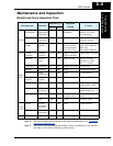
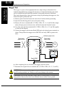
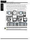
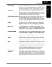
Inverter Output Voltage Measurement Techniques
Taking voltage measurements around drives equipment requires the right equipment and
a safe approach. You are working with high voltages and high-frequency switching
waveforms that are not pure sinusoids. Digital voltmeters will not usually produce
reliable readings for these waveforms. And, it is usually risky to connect high voltage
signals to oscilloscopes. The inverter output semiconductors have some leakage, and
no-load measurements produce misleading results. So, we highly recommend using the
following circuits to measure voltage for performing the equipment inspections.
HIGH VOLTAGE: Be careful not to touch wiring or connector terminals when working
with the inverters and taking measurements. Be sure to place the measurement circuitry
components above in an insulated housing before using them.
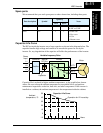
220 kΩ
2W
+–
220 kΩ
2W
+–
Voltage measurement with load
Inverter
Voltage measurement without load
Additional resistor
Inverter
5 kΩ
30W
V Class Diode Bridge Vol tmeter
200V Class 600V 0.01A min. 300V range
400V Class 100V 0.1A min. 600V range
V Class Diode Bridge Voltmeter
200V Class 600V 0.01A min. 300V range
400V Class 100V 0.1A min. 600V range
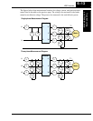
L1/R
L2/S
L3/T
U/T1
V/T2
W/T3
L1/R
L2/S
L3/T
U/T1
V/T2
W/T3