


L200 Inverter
Appendix B
B–33
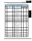
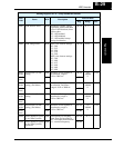
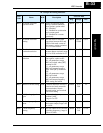
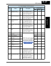
B021 Overload restriction
operation mode
R/W Select the operating mode
during overload conditions,
three options, option codes:
00...Disabled
01...Enabled for acceleration
and constant speed
02...Enabled for constant
speed only
0092h 0, 1, 2 —
B022 Overload restriction
setting
R/W Sets the level for overload
restriction, between 20% and
150% of the rated current of
the inverter, setting resolution
is 1% of rated current
0093h 2000 to
15000
0.01%
B023 Deceleration rate at
overload restriction
R/W Sets the deceleration rate when
inverter detects overload, range
is 0.1 to 30.0, resolution is 0.1
0094h 1 to 300 0.1 sec
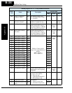
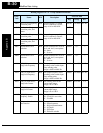
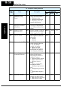
B031 Software lock mode
selection
R/W Prevents parameter changes, in
four options, option codes:
00...all parameters except
B031 are locked when [SFT]
terminal is ON
01...all parameters except
B031 and output frequency
F001 when [SFT] terminal is
ON
02...all parameters except
B031 are locked
03...all parameters except
B031 and output frequency
F001 setting are locked
0095h 0, 1, 2, 3 —
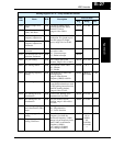
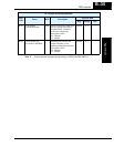
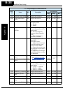
B032 Reactive current setting R/W Calibrate detection of motor’s
reactive (no load) current for
current monitor, electric
thermal setting, and overload
restriction setting
00E8h 50 to
200
1%
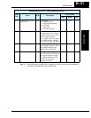
B080 [AM] analog signal
gain
R/W Adjust of analog output at
terminal [AM],
range is 0 to 255
0096h 0 to 255 —
B082 Start frequency adjust-
ment
R/W Sets the starting frequency for
the inverter output, range is 0.5
to 9.9 Hz
0098h 5 to 99 0.1 Hz
B083 Carrier frequency
setting
R/W Sets the PWM carrier (internal
switching frequency), range is
2.0 to 14.0 kHz
0099h 20 to
140
0.1 Hz
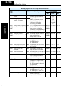
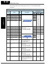
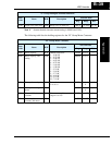
“B” Group Fine Tuning Functions
Func.
Code
Name R/W Description
Network Data
Reg. Range Res.