


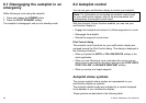
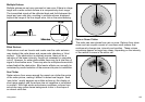
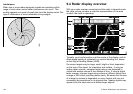
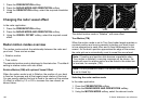
Interference
When two or more radar-equipped vessels are operating within
range of each other mutual radar interference can occur. This
usually appears as a spiral of small dots from the display centre This
type of interference is most noticeable at long ranges.
D6601-2
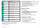
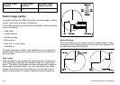
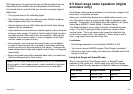
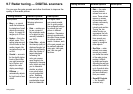
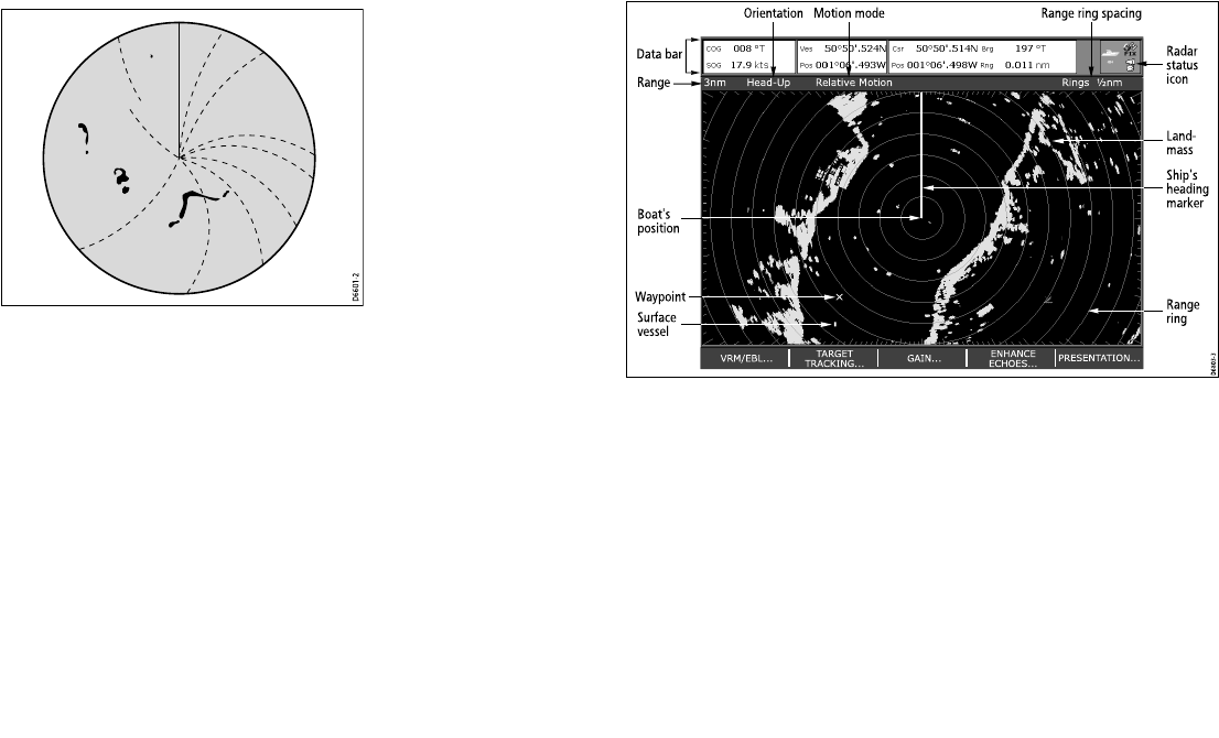
9.4 Radar display overview
With your radar scanner connected and the radar in transmit mode,
the radar picture provides a map-like representation of the area
in which the radar is operating.
3nm
Head-Up Relativ e Motion Rings ½ nm
VRM/EBL... GAIN...
PRESENT ATION...
TARGET
TRACKING...
ENHANCE
ECHOES ...
D6803-3
Orientation
Data bar
Surface
vessel
Waypoint
Ship's
heading
marker
Radar
status
icon
Range
ring
Land-
mass
Boat's
position
Range
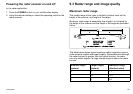
Motion mode Range ring spacing
Typically, your boat’s position is at the centre of the display, and its
dead ahead bearing is indicated by a vertical heading line, known
as the Ship’s Heading Marker (SHM).
On-screen targets may be large, small, bright or faint, dependent
on the size of the object, its orientation and surface. If using an
analog radar scanner, strongest target returns are displayed in
yellow with weaker returns in two shades of blue. If using a digital
radar scanner, stronger target returns show as different colors from
a range of 256 colors, providing better clarity. Be aware that the size
of a target on screen is dependent on many factors and may not
necessarily be proportional to its physical size. Nearby objects may
appear to be the same size as a distant larger objects.
104 C-Series Widescreen user reference