


PowerLogic™ PM5500 series user manual Chapter 15—Verifying accuracy
HRB1684301-01 129
Verifying accuracy test
The following are guidelines for testing the meter; your meter shop may have specific
testing methods.
1. Turn off power to all test equipment. Use a properly rated voltage sensing device to
confirm power is off.
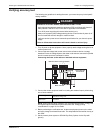
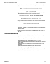
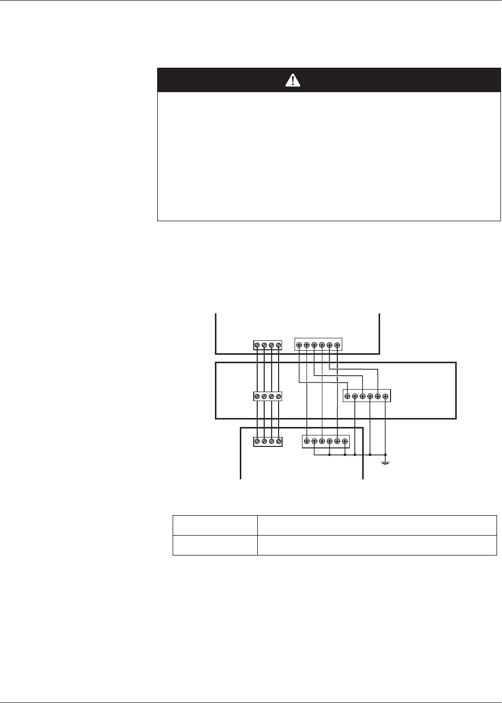
2. Connect the test voltage and current source to the reference device or energy
standard. Ensure all voltage inputs to the meter under test are connected in parallel
and all currents inputs are connected in series.
3. Connect the control equipment used for counting the standard output pulses using
one of these methods:
NOTE: When selecting which method to use, be aware that the Alarm / energy LED
and digital outputs have different pulse rate limits. See “Energy pulsing
considerations” on page 131 for details.
4. Before performing the verification test, let the test equipment power up the meter
and apply voltage for at least 30 seconds. This helps stabilize the internal circuitry of
the meter.
5. Set the meter’s power system to 3PH4W Wye Gnd (3-phase, 4 wire Wye with
ground).
DANGER
HAZARD OF ELECTRIC SHOCK, EXPLOSION OR ARC FLASH
• Apply appropriate personal protective equipment (PPE) and follow safe electrical
work practices. See NFPA 70E in the USA or applicable local standards.
• Turn off all power supplying this device before working on it.
• Always use a properly rated voltage sensing device to confirm that all power is off.
• Do not exceed the device’s ratings for maximum limits.
• Verify the device’s power source meets the specifications for your device’s power
supply.
Failure to follow these instructions will result in death or serious injury.
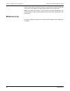
Connecting the meter to the reference standard and test equipment
Alarm / energy LED
Align the red light sensor on the standard test bench armature over the front
panel alarm / energy LED.
Digital output
Connect the meter’s digital output to the standard test bench pulse counting
connections.
V1V2 V3VN
I1 I2 I3
+
-
+
-
+
-
V1V2 V3VN
I1 I2 I3
+
-
+
-
+
-
V1V2 V3VN
I1 I2 I3
+
-
+
-
+
-
Reference device or energy standard
Meter under test
Test voltage and
current source