


20 HRB1684301-01
Chapter 2—Hardware reference PowerLogic™ PM5500 series user manual
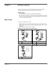
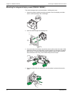
Meter wiring
For wiring instructions and safety precautions, see the meter installation sheet that was
shipped with your meter, or download a copy at www.schneider-electric.com.
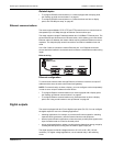
• Wire connections to the meter’s voltage inputs, control power, digital outputs, digital
(status) inputs and RS-485 communications are terminated using the supplied
pluggable wire connectors.
• When wiring the meter’s current inputs, terminate the wire ends with ring or split-ring
crimp connectors.
Use the meter installation sheet when wiring the meter.
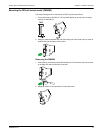
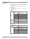
Power system
This section outlines typical requirements for wiring the voltage and current inputs of
the meter to the electrical power system.
For wiring instructions and safety precautions, see the meter installation sheet that was
shipped with your meter, or download a copy at www.schneider-electric.com.
Related topics
• See “Specifications” on page 27 for voltage and current input limits.
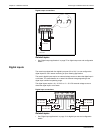
Direct connect voltage limits
You can connect the meter’s voltage inputs directly to the phase voltage lines of the
power system if the power system’s line-to-line or line-to-neutral voltages do not
exceed the meter’s direct connect maximum voltage limits. The meter's voltage
measurement inputs are rated by the manufacturer for up to 400 V L-N / 690 V L-L.
However, the maximum voltage allowed for direct connection may be lower, depending
on the local electrical codes and regulations. In US and Canada the maximum voltage
on the meter voltage measurement inputs may not exceed 347 V L-N / 600 V L-L.
If your system voltage is greater than the specified direct connect maximum voltage,
you must use VTs (voltage transformers) to step down the voltages.
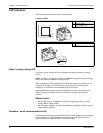
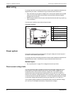
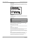
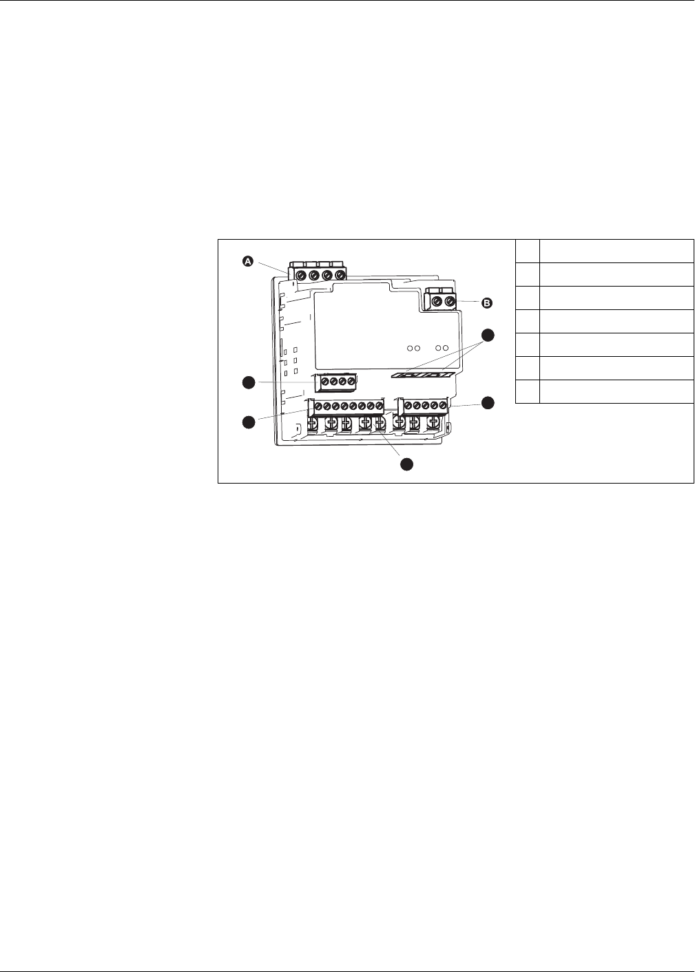
Connector locations
A
Voltage inputs
B
Control power
C
Ethernet ports
D
Digital outputs
E
Current inputs
F
Digital (status) inputs
G
RS-485 port
C
D
E
F
G