


36 HRB1684301-01
Chapter 3—Front panel display and meter setup PowerLogic™ PM5500 series user manual
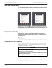
1. Navigate to Maint > Setup.
2. Enter the setup password (default is “0”), then press OK.
3. Navigate to Meter > Basic.
4. Move the cursor to point to the parameter you want to modify, then press Edit.
5. Modify the parameter as required, then press OK.
6. Move the cursor to point to the next parameter you want to modify, press Edit,
make your changes, then press OK.
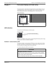
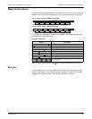
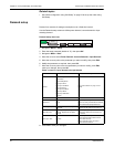
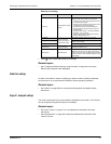
Basic setup menu tree
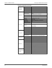
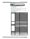
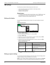
Basic setup parameters
Parameter Values Description
Power System
Select the power system type (power transformer) the meter is wired to.
1PH2W LN Single-phase 2-wire line-to-neutral
1PH2W LL Single-phase 2-wire line-to-line
1PH3W LL with N Single-phase 3-wire line-to-line with neutral
3PH3W Dlt Ungnd 3-phase 3-wire ungrounded delta
3PH3W Dlt Crnr Gnd 3-phase 3-wire corner grounded delta
3PH3W Wye Ungnd 3-phase 3-wire ungrounded wye
3PH3W Wye Gnd 3-phase 3-wire grounded wye
3PH3W Wye Res Gnd 3-phase 3-wire resistance-grounded wye
3PH4W Opn Dlt Ctr Tp 3-phase 4-wire center-tapped open delta
3PH4W Dlt Ctr Tp 3-phase 4-wire center-tapped delta
3PH4W Wye Ungnd 3-phase 4-wire ungrounded wye
3PH4W Wye Gnd 3-phase 4-wire grounded wye
3PH4W Wye Res Gnd 3-phase 4-wire resistance-grounded wye
VT Connect
Select how many voltage transformers (VT) are connected to the electrical power
system.
Direct Con Direct connect; no VTs used
2VT 2 voltage transformers
3VT 3 voltage transformers
VT Primary (V) 1 to 1,000,000 Enter the size of the VT primary, in Volts.
VT Secondary (V) 100, 110, 115, 120 Select the size of the VT secondary, in Volts.
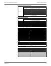
CT on Terminal
Define how many current transformers (CT) are connected to the meter, and
which terminals they are connected to.
I1 1 CT connected to I1 terminal
I2 1 CT connected to I2 terminal
I3 1 CT connected to I3 terminal
I1 I2 2 CT connected to I1, I2 terminals
I1 I3 2 CT connected to I1, I3 terminals
I2 I3 2 CT connected to I2, I3 terminals
I1 I2 I3 3 CT connected to I1, I2, I3 terminals
I1 I2 I3 IN 4 CT connected to I1, I2, I3, IN terminals
CT Primary (A) 1 to 1000000 Enter the size of the CT primary, in Amps.
CT Secondary (A) 1, 5 Select the size of the CT secondary, in Amps.
CT Primary Neu. (A) 1 to 32767
This parameter displays when CT on Terminal is
set to I1,I2,I3, IN. Enter the size of the 4th (Neutral)
CT primary, in Amps.
CT Sec. Neu. (A) 1, 5
This parameter displays when CT on Terminal is
set to I1,I2,I3, IN. Select the size of the 4th
(Neutral) CT secondary, in Amps.
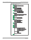
Maint
Reset
Setup Basic
Adv
Dmd
Tariff
Meter