


90 HRB1684301-01
Chapter 10—Alarms PowerLogic™ PM5500 series user manual
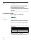
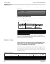
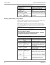
The meter records the date and time when the alarm event starts (EV1) and when it
ends (EV2). The meter also performs any task assigned to the event, such as operating
a digital output. The meter also records maximum values (Max1, Max2) before, during
or after the alarm period.
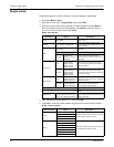
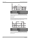
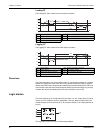
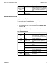
Under setpoint
When the value falls below the pickup setpoint setting and remains there long enough
to satisfy the pickup time delay period (∆T1), the alarm condition is set to ON. When the
value rises above the dropout setpoint setting and remains there long enough to satisfy
the dropout time delay period (∆T2), the alarm condition is set to OFF.
The meter records the date and time when the alarm event starts (EV1) and when it
ends (EV2). The meter also performs any task assigned to the event, such as operating
a digital output. The meter also records minimum values (Min1, Min2) before, during or
after the alarm period.
A Pickup setpoint ∆T2 Dropout time delay (in seconds)
B Dropout setpoint EV2 End of alarm condition
∆T1 Pickup time delay period (in seconds) ∆T3 Alarm duration (in seconds)
EV1 Start of alarm condition Max1 Maximum value recorded during pickup period
Max2 Maximum value recorded during alarm period
A Pickup setpoint ∆T2 Dropout time delay (in seconds)
B Dropout setpoint EV2 End of alarm condition
∆T1 Pickup delay period (in seconds) ∆T3 Alarm duration (in seconds)
EV1 Start of alarm condition Min1 Minimum value recorded during pickup period
Min2 Minimum value recorded during alarm period
EV1
EV2
B
A
ΔT1
ΔT2
ΔT3
Max1
Max2
EV1
EV2
ΔT1
ΔT2
A
B
ΔT3
Min1
Min2