


PowerLogic™ PM5500 series user manual Chapter 10—Alarms
HRB1684301-01 91
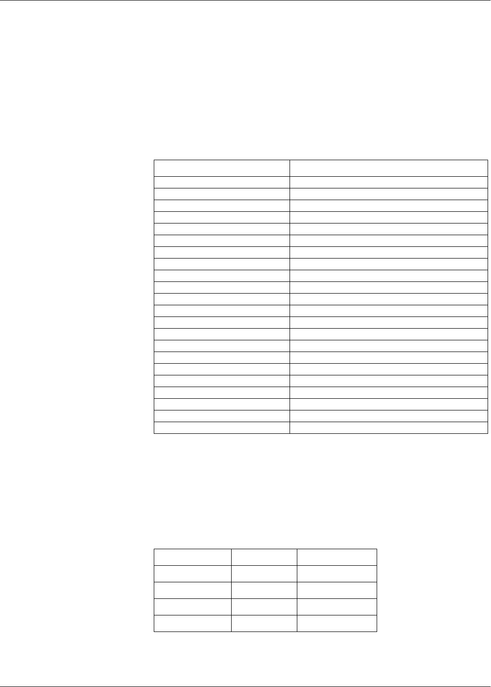
Maximum allowable setpoint
The meter is programmed to help prevent user data entry errors. Limits have been set
for the standard (1-Sec) alarms.
The maximum setpoint value you can enter for some of the standard alarms depend on
the voltage transformer ratio (VT ratio), current transformer ratio (CT ratio), system type
(i.e., number of phases) and/or the maximum voltage and maximum current limits
programmed at the factory.
NOTE: VT ratio is the VT primary divided by the VT secondary, and CT ratio is the CT
primary divided by the CT secondary.
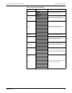
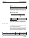
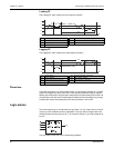
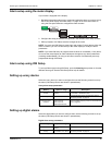
Power factor (PF)
You can set up a Leading PF or Lagging PF alarm to monitor when the circuit’s power
factor goes above or below the threshold you specify. The Leading PF and Lagging PF
alarms use the power factor quadrants as the values on the y-axis, with quadrant II on
the lowest end of the scale, followed by quadrant III, quadrant I, and finally quadrant IV
on the highest end of the scale.
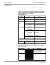
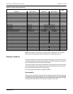
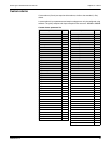
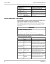
Standard alarm maximum setpoint values
Standard alarm Maximum setpoint value
Over Phase Current (maximum current) x (CT ratio)
Under Phase Current (maximum current) x (CT ratio)
Over Neutral Current (maximum current) x (CT ratio) x (number of phases)
Over Ground Current (maximum current) x (CT ratio)
Over Voltage L-L (maximum voltage) x (VT ratio)
Under Voltage L-L (maximum voltage) x (VT ratio)
Over Voltage L-N (maximum voltage) x (VT ratio)
Under Voltage L-N (maximum voltage) x (VT ratio)
Over Active Power (maximum voltage) x (maximum current) x (number of phases)
Over Reactive Power (maximum voltage) x (maximum current) x (number of phases)
Over Apparent Power (maximum voltage) x (maximum current) x (number of phases)
Over Present Active Power Demand (maximum voltage) x (maximum current) x (number of phases)
Over Last Active Power Demand (maximum voltage) x (maximum current) x (number of phases)
Over Predicted Active Power Demand (maximum voltage) x (maximum current) x (number of phases)
Over Present Reactive Power Demand (maximum voltage) x (maximum current) x (number of phases)
Over Last Reactive Power Demand (maximum voltage) x (maximum current) x (number of phases)
Over Predicted Reactive Power Demand (maximum voltage) x (maximum current) x (number of phases)
Over Present Apparent Power Demand (maximum voltage) x (maximum current) x (number of phases)
Over Last Apparent Power Demand (maximum voltage) x (maximum current) x (number of phases)
Over Predicted Apparent Power Demand (maximum voltage) x (maximum current) x (number of phases)
Over Voltage Unbalance (maximum voltage) x (VT ratio)
Phase Loss (maximum voltage) x (VT ratio)
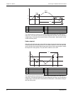
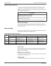
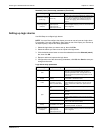
PF quadrants and related values
Quadrant PF values Lead/Lag
II
0 to -1 Leading (capacitive)
III
-1 to 0 Lagging (inductive)
I
0 to 1 Lagging (inductive)
IV
1 to 0 Leading (capacitive)