78 HRB1684301-01
Chapter 8—Input / Output PowerLogic™ PM5500 series user manual
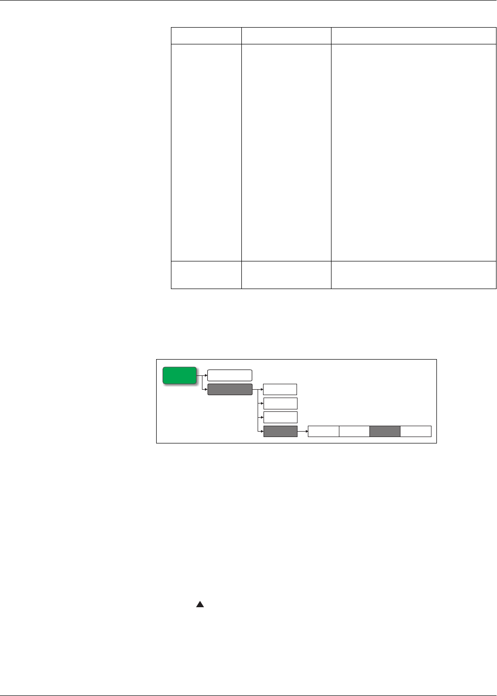
Configuring digital outputs using the front panel
You can use the front panel to configure the digital outputs.
1. Navigate to Maint > Setup.
2. Enter the setup password (default is “0”), then press OK.
3. Navigate to I/O > D Out.
4. Move the cursor to point to the digital output you want to set up, then press Edit.
5. Move the cursor to point to the parameter you want to modify, then press Edit.
NOTE: If Edit is not displayed, it means the parameter is either read-only or can only
be modified through software.
6. Modify the parameter as required, then press OK.
7. Move the cursor to point to the next parameter you want to modify, press Edit,
make your changes, then press OK.
8. Press to exit. Press Yes to save your changes.
Select Alarms
Over Current, Ph; Under
Current, Ph; Over Current,
N; Over Current, Gnd; Over
Voltage, L-L; Under
Voltage, L-L; Over Voltage,
L-N; Under Voltage L-N;
Over kW; Over kVAR; Over
kVA; Lead PF, True; Lag
PF, True; Lead PF, Disp;
Lag PF, Disp; Over kW
Dmd, Pres; Over kW Dmd,
Last; Over kW Dmd, Pred;
Over kVAR Dmd,Pres; Over
kVAR Dmd,Last; Over
kVAR Dmd,Pred; Over kVA
Dmd, Pres; Over kVA Dmd,
Last; Over kVA Dmd, Pred;
Over Frequency; Under
Frequency; Over Voltage
Unbal; Over Voltage THD;
Phase Loss; Meter
Powerup; Meter Reset;
Meter Diagnostic; Phase
Reversal; Digital Alarm S1
through S4; Custom Alarm
1 through 5; Logic Alarm 1
through 10
Applies when Control Mode is set to Alarm. Select
one or more alarms to monitor.
Associations —
This field displays additional information if the digital
output is already associated with another meter
function.
Digital output setup menu tree
Digital output setup parameters available through ION Setup (Continued)
Parameter Values Description
Maint
Reset
Setup
LED D In
D Out
Inp Mtr
Comm
Alarm
I/O
Meter
