PowerLogic™ PM5500 series user manual Chapter 2—Hardware reference
HRB1684301-01 21
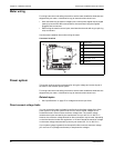
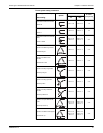
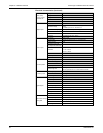
Power system setup parameters
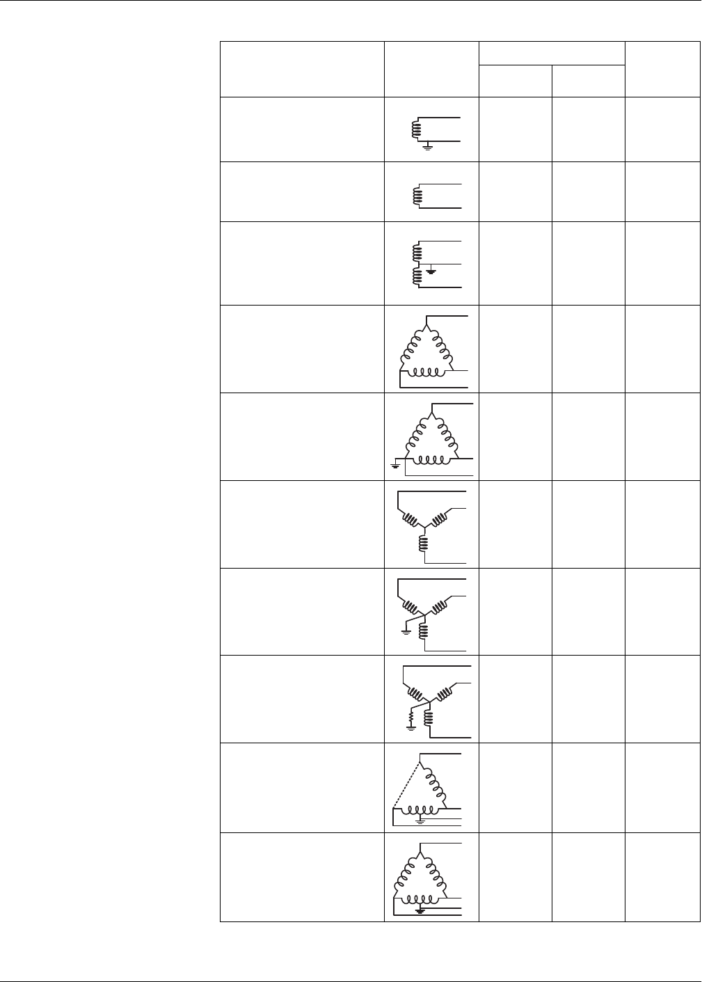
Power system description
—
Meter setting
Symbol
Direct connect maximum
# of VTs
(if required)
UL IEC
Single-phase 2-wire line-to-neutral
—
1PH2W LN
480 V L-N 480 V L-N 1 VT
Single-phase 2-wire line-to-line
—
1PH2W LL
600 V L-L 600 V L-L 1VT
Single-phase 3-wire line-to-line with
neutral
—
1PH3W LL with N
347 V L-N /
600 V L-L
400 V L-N /
690 V L-L
2VT
3-phase 3-wire Delta ungrounded
—
3PH3W Dlt Ungnd
600 V L-L 600 V L-L 2 VT
3-phase 3-wire Delta corner
grounded
—
3PH3W Dlt Crnr Gnd
600 V L-L 600 V L-L 2 VT
3-phase 3-wire Wye ungrounded
—
3PH3W Wye Ungnd
600 V L-L 600 V L-L 2 VT
3-phase 3-wire Wye grounded
—
3PH3W Wye Gnd
600 V L-L 600 V L-L 2 VT
3-phase 3-wire Wye resistance-
grounded
—
3PH3W Wye Res Gnd
600 V L-L 600 V L-L 2 VT
3-phase 4-wire open Delta center-
tapped
—
3PH4W Opn Dlt Ctr Tp
240 V L-N /
415 V L-N /
480 V L-L
240 V L-N /
415 V L-N /
480 V L-L
3 VT
3-phase 4-wire Delta center-tapped
—
3PH4W Dlt Ctr Tp
240 V L-N /
415 V L-N /
480 V L-L
240 V L-N /
415 V L-N /
480 V L-L
3 VT
N
N


