


Reference Manual
00809-0100-4021, Rev DA
November 2004
Rosemount 3144P
1-2
Appendix A: Specifications and Reference Data
• Specifications
• Dimensional drawings
• Ordering Information
Appendix B: Approvals
• Product Certifications
• Installation Drawings
Safety Instrumented System (SIS) – HART only
• Information regarding Safety Certified transmitters
Transmitter Features of the Rosemount 3144P include:
• Accepts inputs from a wide variety of sensors
• Configuration using HART protocol or F
OUNDATION fieldbus
• Electronics that are completely encapsulated in epoxy and enclosed in
a metal housing, making the transmitter extremely durable and
ensuring long-term reliability
• A compact size and two housing options allowing mounting flexibility for
the control room or the field
• Special dual-sensor features include Hot Backup
®
, sensor drift alarm,
first good, differential and average temperature measurements, and
four simultaneous measurement variable outputs in addition to the
analog output signal
Refer to the following literature for a full range of compatible connection
heads, sensors, and thermowells provided by Emerson Process
Management.
• Temperature Sensors and Assemblies Product Data Sheet, Volume 1
(document number 00813-0100-2654)
• Temperature Sensors and Assemblies Product Data Sheet, Metric
(document number 00813-0200-2654)
CONSIDERATIONS
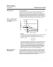
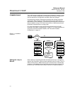
General Electrical temperature sensors, such as resistance temperature detectors
(RTDs) and thermocouples (T/Cs), produce low-level signals proportional to
temperature. The 3144P transmitter converts low-level signals to HART or
F
OUNDATION fieldbus signals. This signal is then transmitted to the control
room via two power/signal wires.
Electrical Proper electrical installation is essential to prevent errors due to sensor lead
resistance and electrical noise. The current loop must have between 250 and
1100 ohms resistance for HART communications. Refer to Figure 2-10 on
page 2-11 for sensor and current loop connections. F
OUNDATION fieldbus
devices must have proper termination and power conditioning for reliable
operation. Shield cables must be used for F
OUNDATION fieldbus and the shield
may only be grounded in one place.