


Reference Manual
00809-0100-4021, Rev DA
November 2004
Rosemount 3144P
3-14
HART
5. Select OK to return the control loop to automatic control. Select HOME
to return to the Home screen.
6. From the Home screen, select 1 Device Setup, 3 Configuration, 2
Sensor Configuration, 1 Change Type and Conn, 3 Sensor 1 Setup to
configure Sensor 1.
7. Set the sensor type, number of wires, damping, and units for Sensor 1.
8. Select SEND to download the new data to the transmitter. Select HOME
to return to the Home screen.
9. Repeat steps 6 – 8 for Sensor 2 using 4 Sensor 2 setup.
10. From the Home screen select 1 Device Setup, 3 Configuration, 3
Dual-Sensor Configuration, 5 Drift Alert to prepare to configure the
transmitter for Drift Alert.
11. Select 2 Drift Limit. Enter the maximum acceptable difference between
Sensor 1 and Sensor 2.
12. Select 3Drift Damping to enter a drift alert damping value. This value
must be between 0 and 32 seconds.
13. Select 1 Drift Alert Option and select Enable Alarm or Warning only.
14. Select SEND to download the alarm setting to the transmitters.
NOTE
Enabling Drift Alert Option Warning only (Step 13) will set a flag (via HART)
whenever the maximum acceptable difference between Sensor 1 and Sensor
2 has been exceeded. If it is desired for the transmitter’s analog signal to go
into alarm when Drift Alert is detected, select Alarm in Step 13.
AMS
For AMS, configure each sensor as indicated above.
Right click on the device and select “Configuration Properties” from the
menu. Select the Dual Sensor tab to configure the Sensor Drift Alarm. In
the Drift Alert box, enable the Drift Alert Option. Enter the DrftLm limit and
define the Drift Limit Units. Set damping if applicable.
Apply changes made (see “Apply AMS Changes” on page 3-5).
DEVICE OUTPUT
CONFIGURATION
Device output configuration contains PV range values, alarm and saturation,
HART output, and LCD display options.
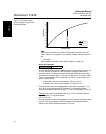
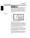
PV Range Values
The PV URV and PV LRV commands, found in the PV Range Values menu
screen, allow the user to set the transmitter’s lower and upper range values
using limits of expected readings. See Table A-2 on page A-5 for unit and
range setting limits. The range of expected readings is defined by the Lower
Range Value (LRV) and Upper Range Value (URV). The transmitter range
values may be reset as often as necessary to reflect changing process
conditions. From the PV Range Values screen select 1 PV LRV to change the
lower range value and 2 PV URV to change the upper range value.
HART Fast Keys 1, 3, 4, 1