


Reference Manual
00809-0100-4021, Rev DA
November 2004
2-9
Rosemount 3144P
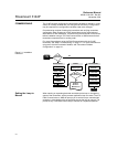
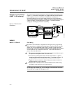
LCD Display Transmitters ordered with the LCD display option (code M5) are shipped with
the LCD display installed. After-market installation of the LCD display on a
conventional 3144P transmitter requires a small instrument screwdriver and
the LCD display kit, which includes:
• LCD display assembly
• Extended cover with cover O-ring in place
• Captive screws (quantity 2)
• 10-pin interconnection header
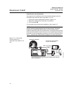
Use the following procedure to install the LCD display. Once the LCD display
is installed, configure the transmitter to recognize the meter option. Refer to
“LCD Meter Options” on page 3-19 (HART) or “LCD Transducer Block” on
page 4-11 (F
OUNDATION fieldbus).
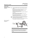
1. If the transmitter is installed in a loop, set the loop to manual (HART) /
out-of-service (F
OUNDATION Fieldbus) mode and disconnect the power.
2. Remove the housing cover from the electronics side of the transmitter.
Do not remove the transmitter covers in explosive atmospheres if the
circuit is live.
3. Ensure that the transmitter write protect switch is set to the Off position.
If transmitter security is On, then you will not be able to configure the
transmitter to recognize the LCD display. If security On is desired, first
configure the transmitter for the LCD display and then install the meter.
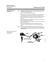
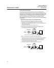
4. Insert the interconnection header in the 10-pin socket on the face of the
electronics module. Insert the pins into the electronics LCD interface.
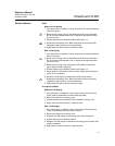
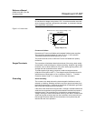
5. Orient the meter. The meter can be rotated in 90-degree increments for
easy viewing. Position one of the four 10-pin sockets on the back of the
meter to accept the interconnection header.
6. Attach the LCD display assembly to the interconnection pins. Thread and
tighten the LCD display screws into the holes on the electronics module.
7. Attach the extended cover; tighten at least one-third turn after the O-ring
contacts the transmitter housing. Both transmitter covers must be fully
engaged to meet explosion proof requirements.
8. Apply power and set the loop to automatic (HART) / in-service
(F
OUNDATION Fieldbus) mode.
NOTE
Observe the following LCD display temperature limits:
Operating:–4 to 185 °F (–20 to 85 °C)
Storage:–50 to 185 °F (–45 to 85 °C)