


Reference Manual
00809-0100-4021, Rev DA
November 2004
6-5
Rosemount 3144P
Certified SIS
3144P SIS Fast Key
Sequences
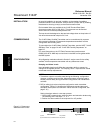
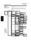
Fast key sequences are listed below for 3144P SIS Safety Certified
transmitter functions.
NOTE:
Table 6-1 provides alphabetical function lists for all Field Communicator tasks
as well as their corresponding fast key sequences.
For the 3144P transmitter, see “Fast Key Sequences” on page 3-4.
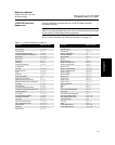
Table 6-1. 3144P SIS Fast Key Sequence
Function HART Fast Keys Function HART Fast Keys
Active Calibrator 1, 2, 2, 1, 3 Open Sensor Holdoff 1, 3, 6, 4
Alarm Values 1, 3, 4, 2, 1 Percent Range 1, 1, 5
Analog Output 1, 1, 4 Poll Address 1, 3, 4, 3, 1
Average Temperature Setup 1, 3, 3, 2 Process Temperature 1, 1
Average Temperature Configuration 1, 3, 3, 2 Process Variables 1, 1
Burst Mode 1, 3, 4, 3, 3 Range Values 1, 3, 4, 1
Burst Option 1, 3, 4, 3, 4 Review 1, 4
Calibration 1, 2, 2 Scaled D/A Trim 1, 2, 2, 3
Clear Log 1, 2, 1, 6 Sensor 1 Configuration 1, 3, 2, 3
Configure Hot Backup 1, 3, 3, 4 Sensor 2 Configuration 1, 3, 2, 4
Configuration 1, 3 Sensor Limits 1, 3, 2, 2
D/A Trim 1, 2, 2, 2 Sensor 1 Serial Number 1, 3, 2, 3, 3
Damping Values 1, 3, 4, 1, 3 Sensor 2 Serial Number 1, 3, 2, 4, 3
Date 1, 3, 5, 2 Sensor 1 Setup 1, 3, 2, 3
Descriptor 1, 3, 5, 3 Sensor 2 Setup 1, 3, 2, 4
Device Information 1, 3, 5 Sensor Trim 1, 2, 2, 1, 1
Diagnostics and Service 1, 2 Sensor Type 1, 3, 2, 1
Differential Temperature Setup 1, 3, 3, 1 Sensor 1 Unit 1, 3, 2, 3, 1
Differential Temperature Configuration 1, 3, 3, 1 Sensor 2 Unit 1, 3, 2, 4, 1
Drift Alert 1, 3, 3, 5 Software Revision 1, 4, 1
Filter 50/60 Hz 1, 3, 6, 1 Status 1, 2, 1, 4
First Good Temperature Setup 1, 3, 3, 3 Tag 1, 3, 5, 1
First Good Temperature Configuration 1, 3, 3, 3 Terminal Temperature Setup 1, 3, 2, 5
Hardware Revision 1, 4, 1 Test Device 1, 2, 1
Hart Output 1, 3, 4, 3 Transmitter-Sensor Matching 1, 3, 2, 1
Intermittent Sensor Detect 1, 3, 6, 2 URV (Upper Range Value) 1, 3, 4, 1, 2
Intermittent Threshold 1, 3, 6, 3 USL (Upper Sensor Limit) 1, 3, 4, 1, 6
Loop Test 1, 2, 1, 1 Variable Mapping 1, 3, 1
LRV (Lower Range Value) 1, 3, 4, 1, 1 View Log 1, 2, 1, 5
LSL (Lower Sensor Limit) 1, 3, 4, 1, 5 Wires 1, 3, 2, 1
Master Reset 1, 2, 1, 3 2-wire Offset Sensor 1 1, 3, 2, 3, 6
Message 1, 3, 5, 4 2-wire Offset Sensor 2 1, 3, 2, 4, 6
Meter Options 1, 3, 4, 4