


Reference Manual
00809-0100-4021, Rev DA
November 2004
Rosemount 3144P
2-6
INSTALLATION
Typical North American
Installation
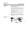
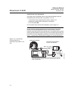
1. Attach the thermowell to the pipe or process container wall. Install and
tighten thermowells and sensors. Apply process pressure to perform a
leak test.
2. Attach necessary unions, couplings, and extension fittings. Seal the
fitting threads with teflon
®
(PTFE) tape (if required).
3. Screw the sensor into the thermowell or directly into the process
(depending on installation requirements).
4. Verify all sealing requirements for severe environments or to satisfy code
requirements.
5. Attach the transmitter to the thermowell/sensor assembly. Seal all
threads with Teflon (PTFE) tape (if required).
6. Pull sensor leads through the extensions, unions, or couplings into the
terminal side of the transmitter housing.
7. Install field wiring conduit to the remaining transmitter conduit entry.
8. Pull the field wiring leads into the terminal side of the transmitter housing.
9. Attach the sensor leads to the transmitter sensor terminals. Attach the
power leads to the transmitter power terminals.
10. Attach and tighten both transmitter covers. Both transmitter covers must
be fully engaged to meet explosion-proof requirements.
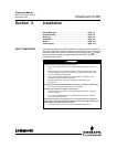
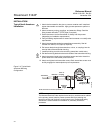
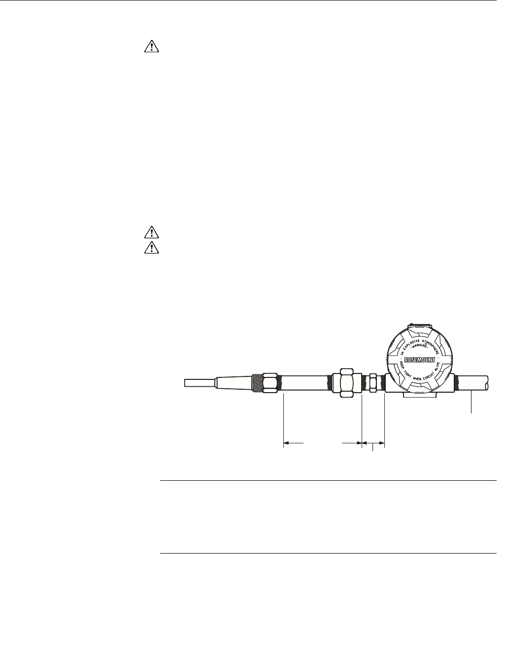
Figure 2-4. Typical North
American Mounting
Configuration.
NOTE
The National Electrical Code requires that a barrier or seal be used in addition
to the primary (sensor) seal to prevent process fluid from entering the
electrical conduit and continuing to the control room. Professional safety
assistance is recommended for installation in potentially hazardous
processes.
Thermowell
Extension
Conduit for Field
Wiring (dc power)
3.2
(81)
Extension
Fitting
Length
Union or
Coupling
NOTE: Dimensions are in inches (millimeters).
3144-0433B