


Reference Manual
00809-0100-4021, Rev DA
November 2004
Rosemount 3144P
5-2
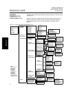
MAINTENANCE The 3144P transmitter has no moving parts and require a minimum amount of
scheduled maintenance. The transmitter features a modular design for easy
maintenance. If a malfunction is suspected, check for an external cause
before performing the diagnostics as discussed in this section.
Test Terminal
(HART / 4–20 mA only)
The test terminal, marked as TEST or (“T”) on the terminal block, and the
negative (-) terminal accept MINIGRABBER
™
, or alligator clips, and facilitate
in-process checks (see Figure 2-8 on page 2-11). The test and the negative
terminals are connected across a diode through which the loop signal current
passes. The current measuring equipment shunts the diode when connected
across the test (T) and negative (-) terminals; so as long as the voltage across
the terminals is kept below the diode threshold voltage, no current passes
through the diode. To ensure that there is no leakage current through the
diode while making a test reading, or while an indicating meter is connected,
the resistance of the test connection or meter should not exceed 10 ohms. A
resistance value of 30 ohms will cause an error of approximately 1.0 percent
of reading.
Sensor Checkout If the sensor is installed in a high-voltage environment and a fault condition or
installation error occurs, the sensor leads and transmitter terminals could
carry lethal voltages. Use extreme caution when making contact with the
leads and terminals.
To determine whether the sensor is at fault, either replace it with another
sensor or connect a test sensor locally at the transmitter to test remote sensor
wiring. Transmitters with Option Code C7 (Trim to Special Sensor), are
matched to a specific sensor. Select any standard, off-the-shelf sensor for use
with the transmitter, or consult the factory for a replacement special
sensor/transmitter combination.
Electronics Housing The transmitter is designed with a dual-compartment housing; one
compartment contains the electronics module, and the other compartment
contains all wiring terminals and the communication receptacles.
Removing the Electronics Module
The 3144P electronics module is located in the compartment opposite the
wiring terminals.
Use the following procedure to remove the electronics module.
NOTE
The electronics are sealed in a moisture-resistant plastic enclosure referred to
as the electronics module. The module is a non-repairable unit; The entire
unit must be replaced if a malfunction occurs.
1. Disconnect the power to the transmitter.
2. Remove the cover from the electronics side of the transmitter housing
(see “ Transmitter Exploded View” on page A-7). Do not remove the
covers in explosive atmospheres when the circuit is live. Remove the
LCD display, if applicable.