


Reference Manual
00809-0100-4021, Rev DA
November 2004
Rosemount 3144P
6-2
Certified SIS
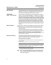
INSTALLATION No special installation is required in addition to the standard installation
practices outlined in this document. Always ensure a proper seal by installing
the electronics housing cover(s) so that metal contacts metal.
Environmental limits are available in the 3144P Product Data Sheet
(document number 00813-0100-4021). This document can be found at
www.rosemount.com/safety/safetytechinfo.htm.
The loop should be designed so the terminal voltage does not drop below 12
Vdc when the transmitter output is 24.5 mA.
COMMISSIONING The 3144P Safety Certified Transmitter can be commissioned by a person
with average knowledge of Rosemount temperature transmitters and the
configuration device being used.
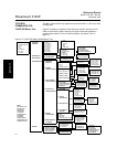
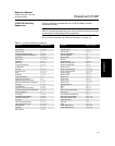
To commission the 3144P Safety Certified Transmitter, use the HART “3144P
SIS Menu Tree” on page 6-4 and “3144P SIS Fast Key Sequences” on
page 6-5.
For more information on the 375 Field Communicator see document
00809-0100-4276. AMS help can be found in the AMS on-line guides within
the AMS system.
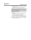
CONFIGURATION All configuration methods outlined in Section 3 are the same for the safety
certified 3144P temperature transmitter with any differences noted.
Damping and Alarm Levels
User-adjustable damping will affect the transmitters ability to respond to
changes in the applied process. The damping value + response time should
not exceed the loop requirements.
NOTES
1. Transmitter output is not safety-rated during the following: configuration
changes, multidrop, and loop test. Alternative means should be used to
ensure process safety during transmitter configuration and maintenance
activities.
2.
DCS or safety logic solver should be configured to match transmitter
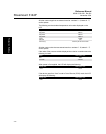
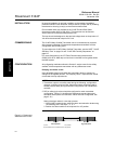
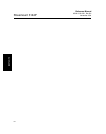
configuration. Figure 6-1 identifies the Rosemount standard alarm and
saturation levels (Alarm and saturation values are user-configurable, see
page 3-16.)
Setting the alarm values is a two step process
1. With a HART communicator, select the alarm and saturation levels using
the following HART fast keys 1, 3, 4, 2.
2. Position the Alarm switch to the required HI or LO position.
Figure 6-1. Rosemount
Standard Alarm Levels
(1) Transmitter Failure, hardware alarm in LO position.
(2) Transmitter Failure, hardware alarm in HI position.
Normal Operation
4 mA
20 mA
20.5 mA
high saturation
21.75
(2)
3.9 mA
low saturation
3.75 mA
(1)