


Reference Manual
00809-0100-4021, Rev DA
November 2004
Rosemount 3144P
3-4
HART
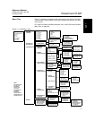
Fast Key Sequences Fast key sequences are listed below for common 3144P transmitter functions.
NOTE:
The fast key sequences assume that “Device Revision Dev v3, DD v2 is being
used. Table 3-1 provides alphabetical function lists for all Field Communicator
tasks as well as their corresponding fast key sequences.
For 3144P SIS Safety Certified transmitter, see “3144P SIS Fast Key
Sequences” on page 6-5.
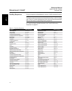
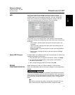
Table 3-1. Fast Key Sequence
Function HART Fast Keys Function HART Fast Keys
Active Calibrator 1, 2, 2, 1, 3 Open Sensor Holdoff 1, 3, 6, 4
Alarm Values 1, 3, 4, 2, 1 Percent Range 1, 1, 5
Analog Output 1, 1, 4 Poll Address 1, 3, 4, 3, 1
Average Temperature Setup 1, 3, 3, 2 Process Temperature 1, 1
Average Temperature Configuration 1, 3, 3, 2 Process Variables 1, 1
Burst Mode 1, 3, 4, 3, 3 Range Values 1, 3, 4, 1
Burst Option 1, 3, 4, 3, 4 Review 1, 4
Calibration 1, 2, 2 Scaled D/A Trim 1, 2, 2, 3
Configure Hot Backup 1, 3, 3, 4 Sensor 1 Configuration 1, 3, 2, 3
Configuration 1, 3 Sensor 2 Configuration 1, 3, 2, 4
D/A Trim 1, 2, 2, 2 Sensor Limits 1, 3, 2, 2
Damping Values 1, 3, 4, 1, 3 Sensor 1 Serial Number 1, 3, 2, 3, 3
Date 1, 3, 5, 2 Sensor 2 Serial Number 1, 3, 2, 4, 3
Descriptor 1, 3, 5, 3 Sensor 1 Setup 1, 3, 2, 3
Device Information 1, 3, 5 Sensor 2 Setup 1, 3, 2, 4
Diagnostics and Service 1, 2 Sensor Trim 1, 2, 2, 1, 1
Differential Temperature Setup 1, 3, 3, 1 Sensor Type 1, 3, 2, 1
Differential Temperature Configuration 1, 3, 3, 1 Sensor 1 Unit 1, 3, 2, 3, 1
Drift Alert 1, 3, 3, 5 Sensor 2 Unit 1, 3, 2, 4, 1
Filter 50/60 Hz 1, 3, 6, 1 Software Revision 1, 4, 1
First Good Temperature Setup 1, 3, 3, 3 Status 1, 2, 1, 4
First Good Temperature Configuration 1, 3, 3, 3 Tag 1, 3, 5, 1
Hardware Revision 1, 4, 1 Terminal Temperature Setup 1, 3, 2, 5
Hart Output 1, 3, 4, 3 Test Device 1, 2, 1
Intermittent Sensor Detect 1, 3, 6, 2 Transmitter-Sensor Matching 1, 3, 2, 1
Intermittent Threshold 1, 3, 6, 3 URV (Upper Range Value) 1, 3, 4, 1, 2
Loop Test 1, 2, 1, 1 USL (Upper Sensor Limit) 1, 3, 4, 1, 6
LRV (Lower Range Value) 1, 3, 4, 1, 1 Variable Mapping 1, 3, 1
LSL (Lower Sensor Limit) 1, 3, 4, 1, 5 Wires 1, 3, 2, 1
Master Reset 1, 2, 1, 3 2-wire Offset Sensor 1 1, 3, 2, 3, 6
Message 1, 3, 5, 4 2-wire Offset Sensor 2 1, 3, 2, 4, 6
Meter Options 1, 3, 4, 4