


Reference Manual
00809-0100-4021, Rev DA
November 2004
3-27
Rosemount 3144P
HART
3. Select temperature units for Channel 1 that match the differential
temperature units of the transmitter.
4. Specify a range for the TV such as –100 to 100 °C. If the range is large,
then a sensor drift of a few degrees will represent only a small percent of
range. If Sensor 1 or Sensor 2 fails, the TV will be +9999 (high
saturation) or –9999 (low saturation). In this example, zero is the
midpoint of the TV range. If a ∆T of zero is set as the lower range limit
(4 mA), then the output could saturate low if the reading from Sensor 2
exceeds the reading from Sensor 1. By placing zero in the middle of the
range, the output will normally stay near 12 mA, and the problem will be
avoided.
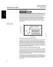
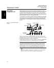
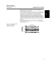
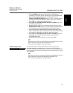
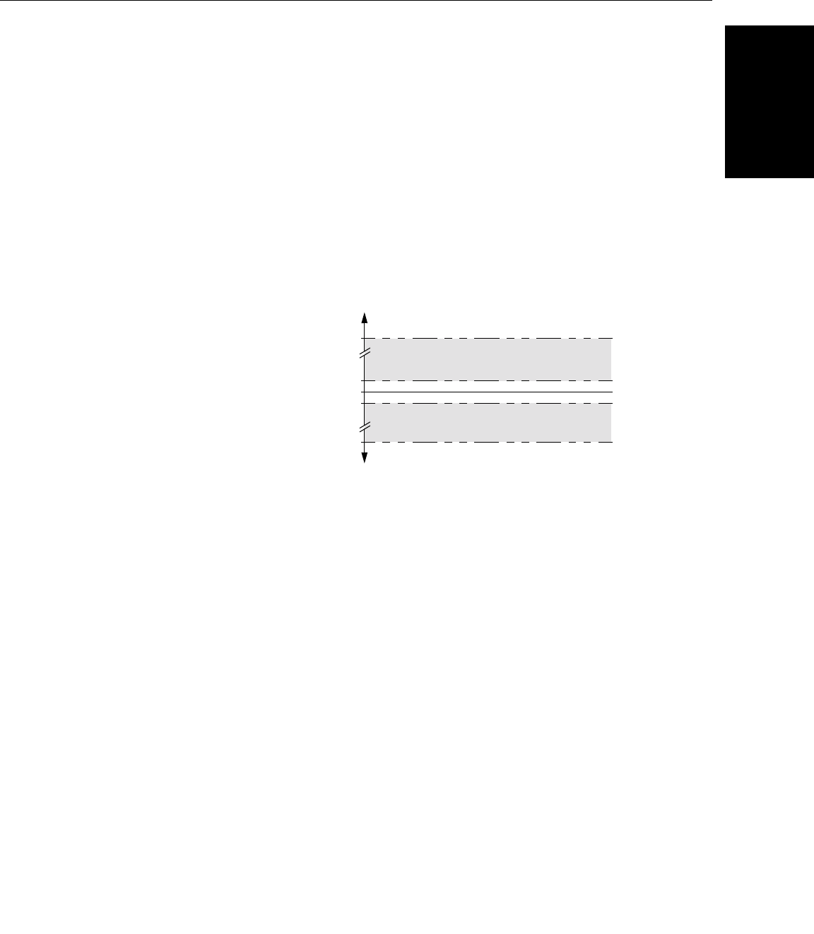
5. Configure the DCS so that TV < –100 °C or TV > 100 °C indicates a
sensor failure and, for example, TV ≤ –3 °C or TV ≥ 3 °C indicates a drift
alert. See Figure 3-5.
Figure 3-5. Tracking Sensor Drift
and Sensor Failure with
Differential Temperature
3 °C
0 °C
–3 °C
100 °C
Sensor Drift
Sensor Drift
Sensor Failure
(Failure Mode Switch HIGH)
DIFFERENTIAL
TEMPERATURE
Sensor Failure
(Failure Mode Switch LOW)
–100 °C