


Reference Manual
00809-0100-4021, Rev DA
November 2004
Rosemount 3144P
A-8
FOUNDATION FIELDBUS
SPECIFICATIONS
Power Supply
Powered over F
OUNDATION Fieldbus with standard fieldbus power supplies.
Transmitters operate on 9.0 to 32.0 V dc, 11 mA maximum. Transmitter power
terminals are rated to 42.4 V dc.
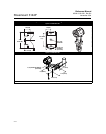
Wiring Diagram
See Figure 2 on page A-13.
Alarms
The AI function block allows the user to configure the alarms to HIGH-HIGH,
HIGH, LOW, or LOW-LOW with a variety of priority levels and hysteresis
settings
Transient Protection (option code T1)
The transient protector helps to prevent damage to the transmitter from
transients induced on the loop wiring by lightning, welding, heavy electrical
equipment, or switch gears. The transient protection electronics are contained
in an add-on assembly that attaches to the standard transmitter terminal
block. The transient terminal block is not polarity insensitive. The transient
protector has been tested to the following standard:
• IEEE C62.41-1991 (IEEE 587), Location Categories B3.
• Combinational Wave, 6kV/3kA peak, 1.2*50uS/8*20uS.
• Ring Wave, 100kHz, 6kV/0.5kA peak
• EFT, 4kV, 2.5kHz, 5*50nS
• Loop resistance added by protector: 22 ohms max.
• Nominal clamping voltages:90 V (common mode),
77 V (normal mode)
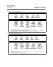
Local Display
Displays all DS_65 measurements in the Transducer and Function Blocks
including Sensor 1, Sensor 2, differential and terminal temperatures. The
display alternates up to four selected items. The meter can display up to five
digits in engineering units (°F, °C, °R, K, Ω, and millivolts). Display settings are
configured at the factory according to the transmitter configuration (standard
or custom). These settings can be reconfigured in the field using a 375 Field
Communicator or DeltaV. In addition, the LCD provides the ability to display
DS_65 parameters from other devices. In addition to the configuration of the
meter, sensor diagnostic data is displayed. If the measurement status is
Good, the measured value is shown. If the measurement status is Uncertain,
the status indicating uncertain is show in addition to the measured value.If the
measurement status is Bad, the reason for the bad measurement is shown.
Note: When ordering a spare electronics module assembly, the LCD
transducer block will display the default parameter.
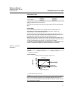
Turn-on Time
Performance within specifications is achieved less than 20 seconds after
power is applied to the transmitter when the damping value is set to 0
seconds.