


Reference Manual
00809-0100-4021, Rev DA
November 2004
3-39
Rosemount 3144P
HART
AMS Software (HART /
4-20 mA only)
If a malfunction is suspected despite the absence of a diagnostics message,
follow the procedures described in Table 3-4 to verify that transmitter
hardware and process connections are in good working order. Under each of
four major symptoms, specific suggestions are offered for solving problems.
Always deal with the most likely and easiest-to-check conditions first.
Advanced troubleshooting information is available in Table 3-5 on page 3-40.
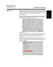
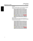
AMS also provides help screens to assist in message communication. See
“When the Drift Alert warning or alarm is enable, they indicate that the
differences between Sensor 1 and Sensor 2 has exceeded the user-specified
limit. One of the sensors may be malfunctioning. The sensors should both be
investigated at the earliest opportunity.” on page 3-42.
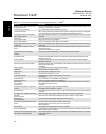
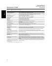
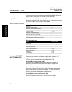
Table 3-4. AMS Basic Troubleshooting
Symptom Potential Source Corrective Action
Transmitter Does Not
Communicate with AMS
Software
Loop Wiring
• Check the revision level of the transmitter device descriptors (DDs) stored in
your software. The communicator should report Dev v3, DD v2 (improved), or
Dev v2, DD v1 (previous). Contact Emerson Process Management Customer
Central for assistance.
• Check for a minimum of 250 ohms resistance between the power supply and
AMS software.
• Check for adequate voltage to the transmitter. If the AMS software is
connected and 250 ohms resistance is properly in the loop, then the transmitter
requires a minimum of 12.0 V at the terminals to operate (over entire 3.90 to
20.5 mA operating range), and 17.5 V minimum to communicate digitally.
• Check for intermittent shorts, open circuits, and multiple grounds.
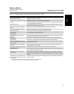
High Output
Sensor Input
Failure or Connection
• Using AMS, set the transmitter test mode to isolate a sensor failure.
• Check for a sensor open circuit.
• Check if the process variable is out of range.
Loop Wiring
• Check for dirty or defective terminals, interconnecting pins, or receptacles.
Power Supply
• Check the output voltage of the power supply at the transmitter terminals. It
should be 12.0 to 42.4 V dc (over entire 3.90 to 20.5 mA operating range).
Electronics Module
• Using AMS, set the transmitter test mode to isolate module failure.
• Using AMS, check the sensor limits to ensure calibration adjustments are
within the sensor range.
Erratic Output
Loop wiring
• Check for adequate voltage to the transmitter. It should be 12.0 to 42.4 V dc at
the transmitter terminals (over entire 3.90 to 20.5 mA operating range).
• Check for intermittent shorts, open circuits, and multiple grounds.
• Using AMS, set the loop test mode to generate signals of 4 mA, 20 mA, and
user-selected values.
Electronics Module
• Using AMS, set the transmitter test mode to isolate module failure.
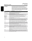
Low Output or No Output
Sensor Element • Using AMS, set the transmitter test mode to isolate a sensor failure.
• Check if the process variable is out of range.
Loop Wiring • Check for adequate voltage to the transmitter. It should be 12.0 to 42.4 V dc
(over entire 3.90 to 20.5 mA operating range).
• Check for shorts and multiple grounds.
• Check for proper polarity at the signal terminal.
• Check the loop impedance.
• Set the loop test mode.
• Check wire insulation to detect possible shorts to ground.
Electronics Module • Using AMS, check the sensor limits to ensure calibration adjustments are within
the sensor range.
• Using AMS, set the transmitter test mode to isolate an electronics module
failure.